5.9.10 Selecting Voltage/Current Input
Signal
The analog input terminals 53 and 54 allow setting of
input signal to voltage (0–10 V) or current (0/4–20 mA).
Default parameter setting:
•
Terminal 53: Speed reference signal in open loop
(see parameter 16-61 Terminal 53 Switch Setting).
•
Terminal 54: Feedback signal in closed loop (see
parameter 16-63 Terminal 54 Switch Setting).
NOTICE
Disconnect power to the drive before changing switch
positions.
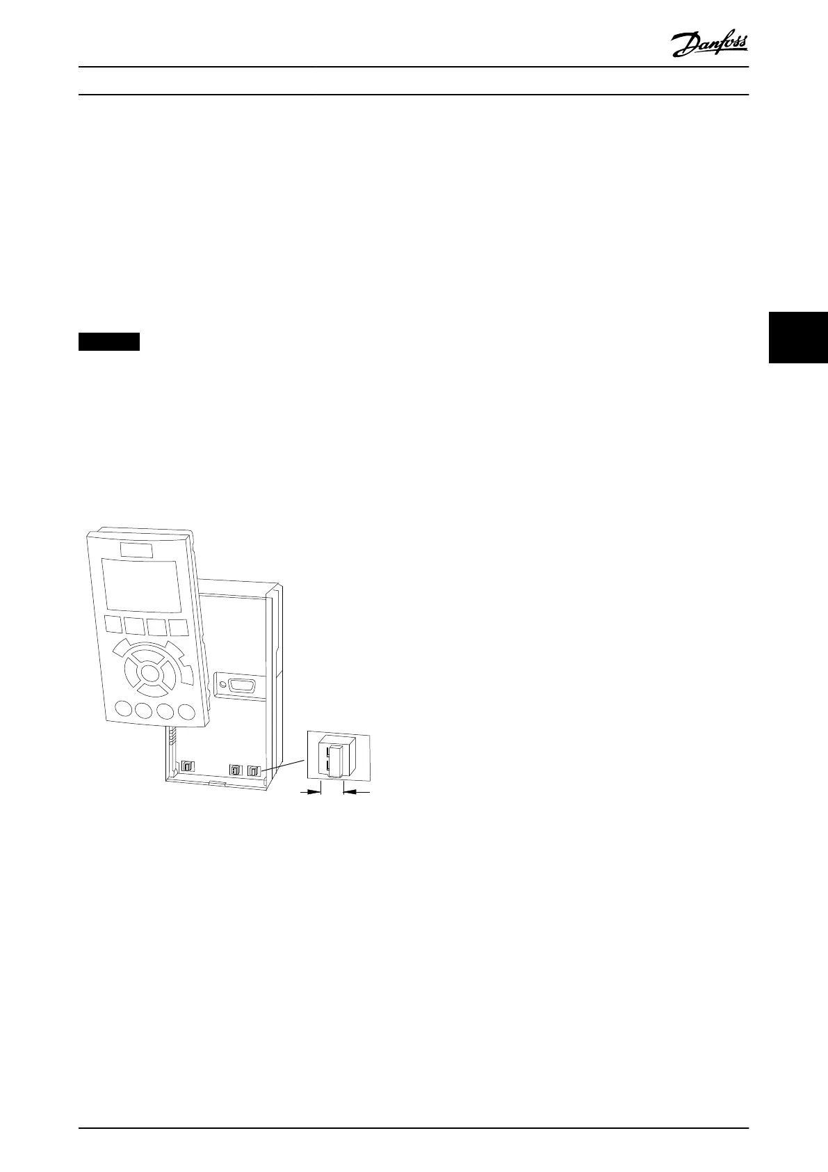
1. Remove the LCP. See Illustration 5.40.
2. Remove any optional equipment covering the
switches.
3. Set switches A53 and A54 to select the signal
type (U = voltage, I = current).
BUS TER.
OFF-ON
A53 A54
U- I U- I
Illustration 5.40 Location of Terminal 53 and 54 Switches
Electrical Installation Operating Guide
MG21A502 Danfoss A/S © 09/2018 All rights reserved. 67
5 5

 Loading...


