2Installation
2.1 Installation Site Check List
•
The frequency converter relies on the ambient air
for cooling. Observe the limitations on ambient air
temperature for optimal operation
•
Ensure that the installation location has sufficient
support strength to mount the frequency converter
•
Keep the frequency converter interior free from
dust and dirt. Ensure that the components stay as
clean as possible. In construction areas, provide a
protective covering. Optional IP55 (NEMA 12) or
IP66 (NEMA 4) enclosures may be necessary.
•
Keep the manual, drawings, and diagrams
accessible for detailed installation and operation
instructions. It is important that the manual is
available for equipment operators.
•
Locate equipment as near to the motor as possible.
Keep motor cables as short as possible. Check the
motor characteristics for actual tolerances. Do not
exceed
•
300m (1000ft) for unshielded motor leads
•
150m (500ft) for shielded cable.
2.2 Frequency Converter and Motor Pre-
installation Check List
•
Compare the model number of unit on the
nameplate to what was ordered to verify the
proper equipment
•
Ensure each of the following are rated for same
voltage:
Mains (power)
Frequency converter
Motor
•
Ensure that frequency converter output current
rating is equal to or greater than motor full load
current for peak motor performance
Motor size and frequency converter
power must match for proper overload
protection
If frequency converter rating is less than
motor, full motor output cannot be
achieved
2.3 Mechanical Installation
2.3.1 Cooling
•
To provide cooling airflow, mount the unit to a
solid flat surface or to the optional back plate (see
2.3.3 Mounting)
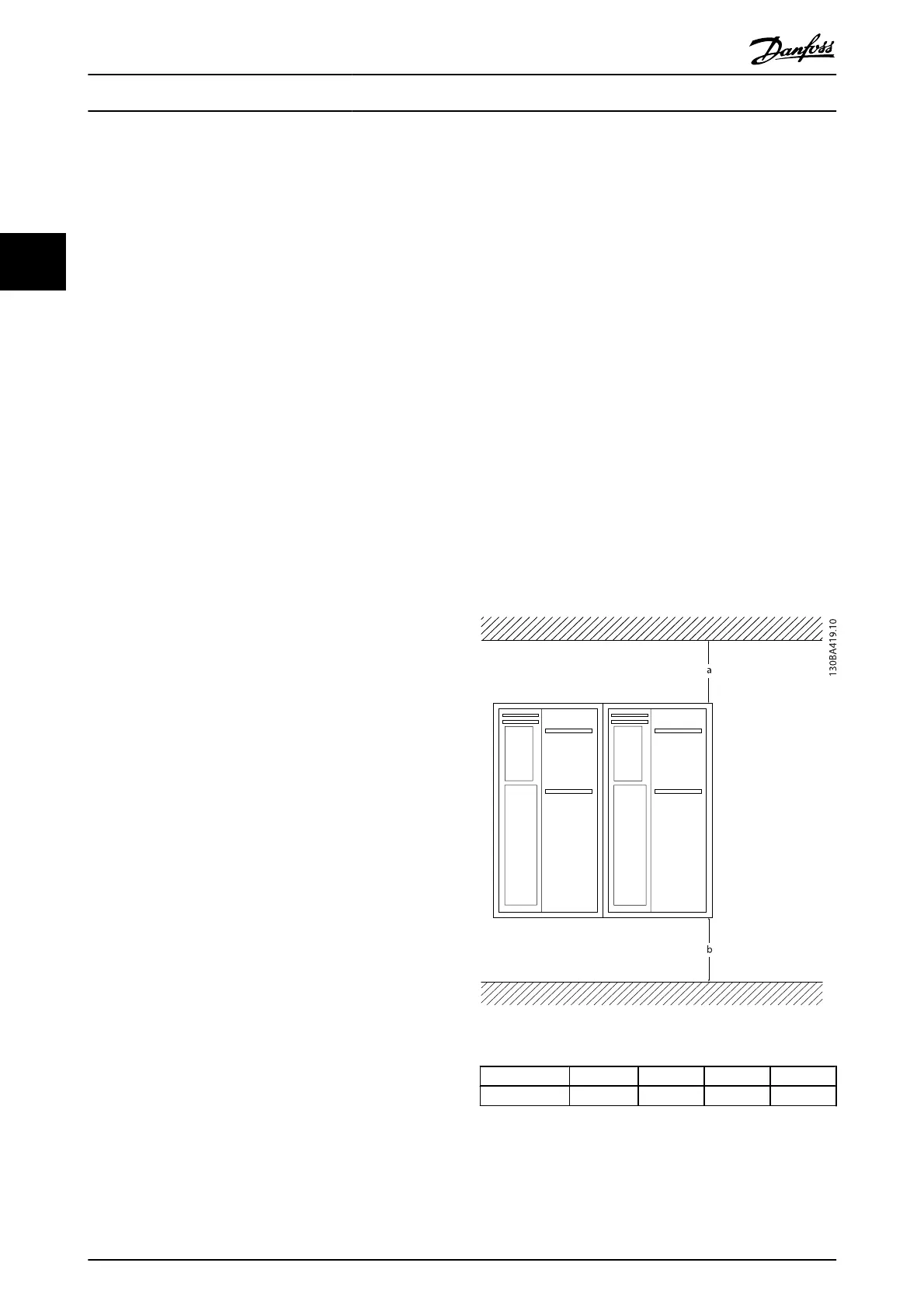
•
Top and bottom clearance for air cooling must be
provided. Generally, 100-225mm (4-10in) is
required. See Illustration 2.1 for clearance
requirements
•
Improper mounting can result in over heating and
reduced performance
•
Derating for temperatures starting between 40°C
(104°F) and 50°C (122°F) and elevation 1000m
(3300ft) above sea level must be considered. See
the equipment Design Guide for detailed
information.
Illustration 2.1 Top and Bottom Cooling Clearance
Enclosure A1-A5 B1-B4 C1, C3 C2, C4
a/b (mm) 100 200 200 225
Table 2.1 Minimum Airflow Clearance Requirements
Installation
VLT
®
AutomationDrive Operating
Instructions
8 MG.33.AJ.02 - VLT
®
is a registered Danfoss trademark
2