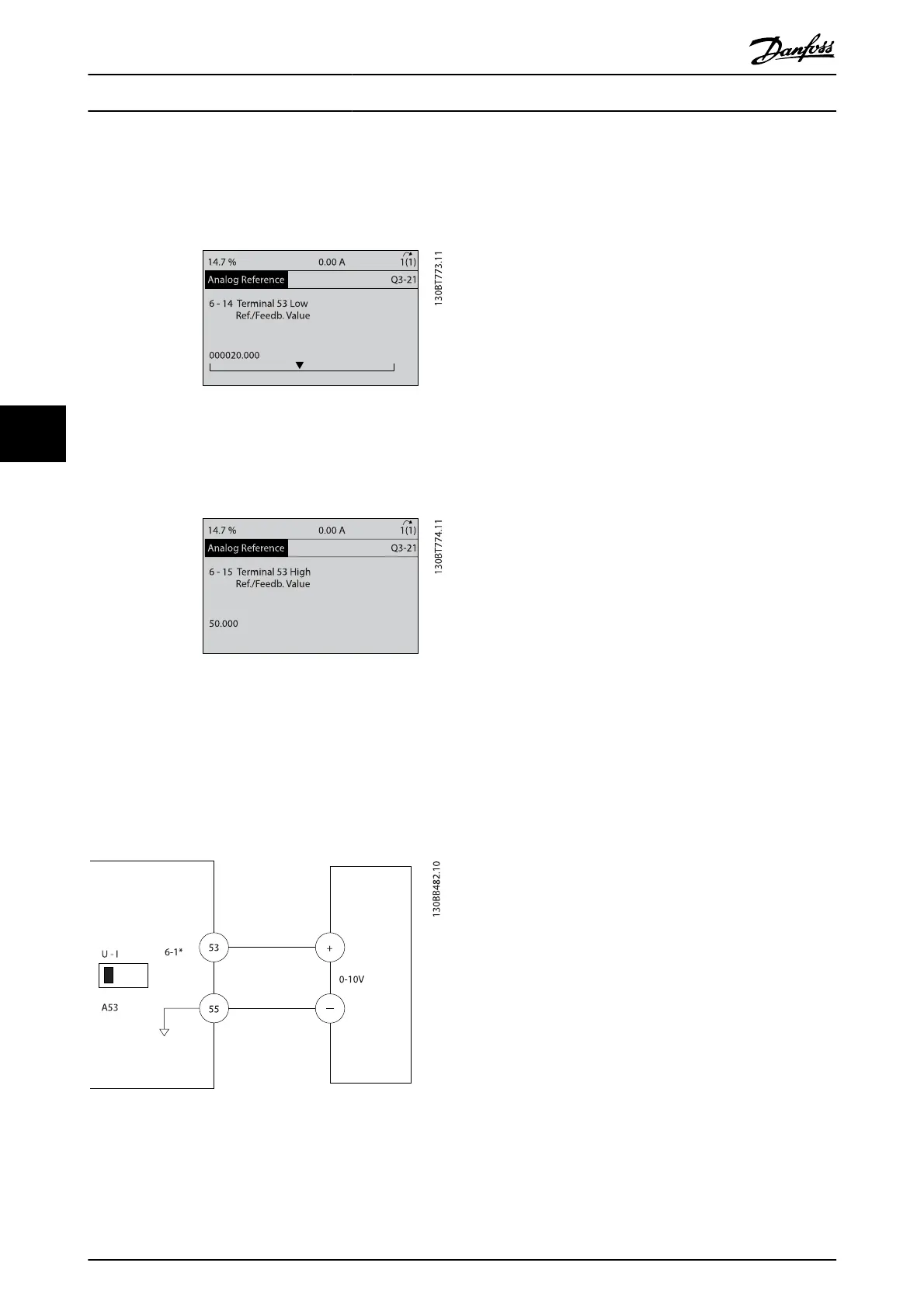
6. 6-14 Terminal 53 Low Ref./Feedb. Value. Set
minimum speed reference on Terminal 53 at 6Hz.
(This tells the frequency converter that the
minimum voltage received on Terminal 53 (0V)
equals 6Hz output.)
7.
6-15 Terminal 53 High Ref./Feedb. Value. Set
maximum speed reference on Terminal 53 at 60Hz.
(This tells the frequency converter that the
maximum voltage received on Terminal 53 (10V)
equals 60Hz output.)
With an external device providing a 0-10V control signal
connected to frequency converter terminal 53, the system is
now ready for operation. Note that the scroll bar on the right
in the last illustration of the display is at the bottom,
indicating the procedure is complete.
Illustration 5.1 shows the wiring connections used to enable
this set up.
Illustration 5.1 Wiring Example for External Device Providing 0-10V
Control Signal (frequency converter left, external device right)
5.3 Control Terminal Programming
Examples
Control terminals can be programmed.
•
Each terminal has specified functions it is capable
of performing
•
Parameters associated with the terminal enable the
function
•
For proper frequency converter functioning, the
control terminals must be
Wired properly
Programmed for the intended function
Receiving a signal
See Table 2.3 for control terminal parameter number and
default setting. (Default setting can change based on the
selection in 0-03 Regional Settings.)
About Frequency Converter P...
VLT
®
AutomationDrive Operating
Instructions
32 MG.33.AJ.02 - VLT
®
is a registered Danfoss trademark
5
 Loading...


