•
Supplemental publications and manuals are
available from Danfoss.
See http://www.danfoss.com/Products/Literature/
Technical+Documentation.htm for listings.
•
Optional equipment is available that may change
some of the procedures described. Be sure to see
the instructions supplied with those options for
specific requirements.
Contact the local Danfoss supplier or go to
http://www.danfoss.com/Products/Literature/Technical
+Documentation.htm for downloads or additional
information.
1.3 Product Overview
A frequency converter is an electronic motor controller that
converts AC mains input into a variable AC waveform output.
The frequency and voltage of the output are regulated to
control the motor speed or torque. The frequency converter
can vary the speed of the motor in response to system
feedback, such as position sensors on a conveyor belt. The
frequency converter can also regulate the motor by
responding to remote commands from external controllers.
In addition, the frequency converter monitors the system
and motor status, issues warnings or alarms for fault
conditions, starts and stops the motor, optimizes energy
efficiency, and offers many more control, monitoring, and
efficiency functions. Operation and monitoring functions are
available as status indications to an outside control system or
serial communication network.
1.4 Internal Frequency Converter Controller
Functions
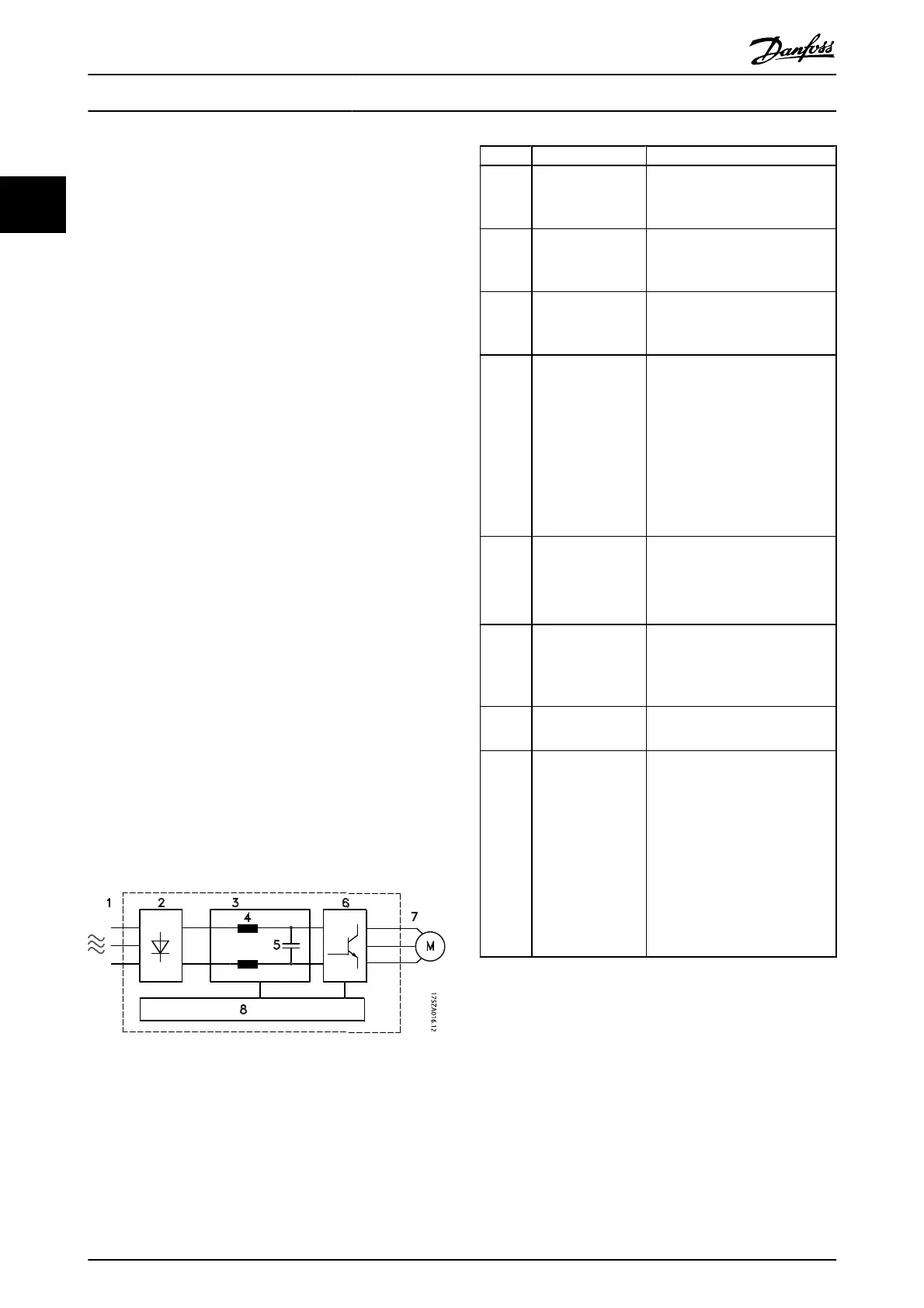
Below is a block diagram of the frequency converter's
internal components. See Table 1.1 for their functions.
Illustration 1.3 Frequency Converter Block Diagram
Area Title Functions
1Mains input
•
Three-phase AC mains power
supply to the frequency
converter
2Rectifier
•
The rectifier bridge converts
the AC input to DC current to
supply inverter power
3DC bus
•
The frequency converter's
intermediate DC-bus circuit
handles the DC current
4DC reactors
•
Filter the intermediate DC
circuit voltage
•
Prove line transient protection
•
Reduce RMS current
•
Raise the power factor
reflected back to the line
•
Reduce harmonics on the AC
input
5 Capacitor bank
•
Stores the DC power
•
Provides ride-through
protection for short power
losses
6Inverter
•
Converts the DC into a
controlled PWM AC waveform
for a controlled variable output
to the motor
7 Output to motor
•
Regulated three-phase output
power to the motor
8 Control circuitry
•
Input power, internal
processing, output, and motor
current are monitored to
provide efficient operation and
control
•
User interface and external
commands are monitored and
performed
•
Status output and control can
be provided
Table 1.1 Frequency Converter Internal Components
Introduction
VLT
®
AutomationDrive Operating
Instructions
6 MG.33.AJ.02 - VLT
®
is a registered Danfoss trademark
1

 Loading...


