Frame IP20 IP21 IP55 IP66
A4/A5 - - 2 2
B1 - * 2.2 2.2
B2 - * 2.2 2.2
C1 - * 2.2 2.2
C2 - * 2.2 2.2
* No screws to tighten
- Does not exist
Table 2.2 Tightening Torques for Covers (Nm)
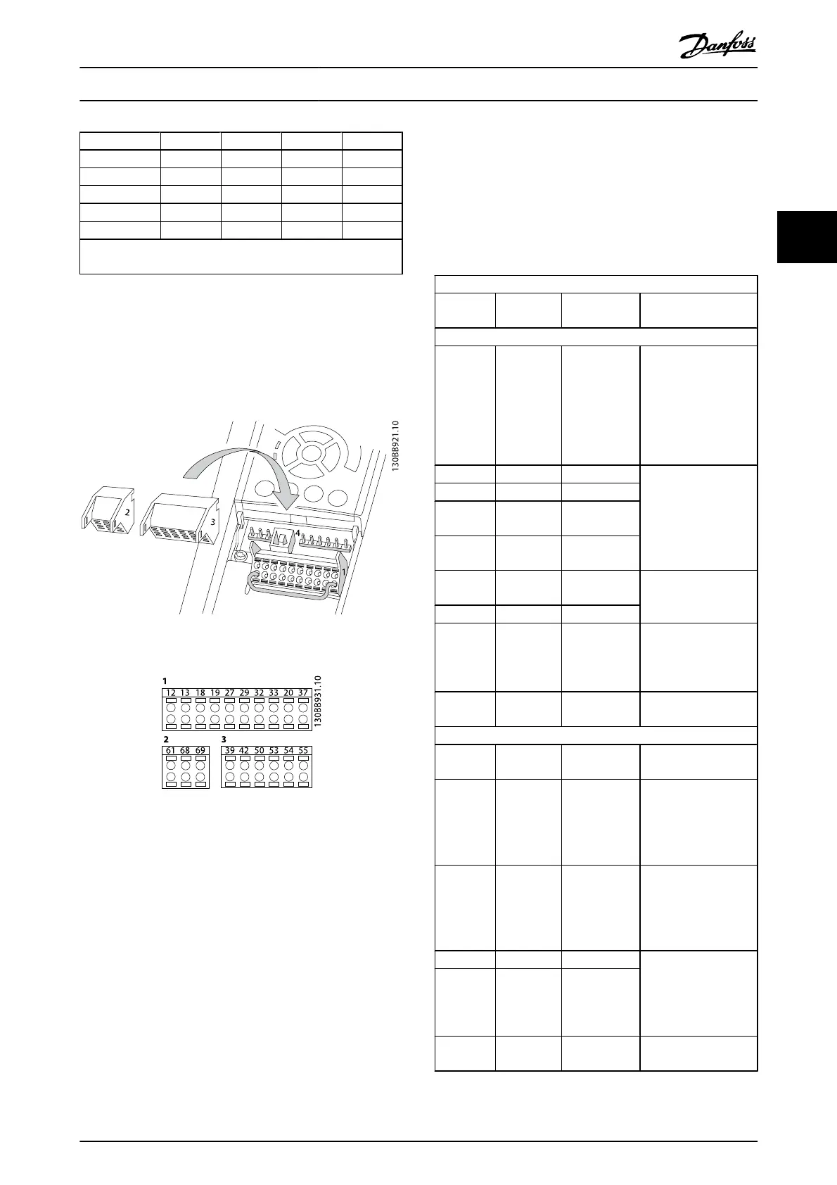
2.4.5.2 Control Terminal Types
Illustration 2.11 and shows the removable frequency
converter connectors. Terminal functions and default
settings are summarized in Table 2.3.
Illustration 2.11 Control Terminal Locations
Illustration 2.12 Terminal Numbers
•
Connector 1 provides four programmable digital
inputs terminals, two additional digital terminals
programmable as either input or output, a 24V DC
terminal supply voltage, and a common for
optional customer supplied 24V DC voltage. FC 302
and FC 301 (optional in A1 enclosure) also provide
a digital input for STO (Safe Torque Off) function.
•
Connector 2 terminals (+)68 and (-)69 are for an
RS-485 serial communications connection
•
Connector 3 provides two analog inputs, one
analog output, 10V DC supply voltage, and
commons for the inputs and output
•
Connector 4 is a USB port available for use with the
MCT 10 Set-up Software
•
Also provided are two Form C relay outputs that
are in various locations depending upon the
frequency converter configuration and size
•
Some options available for ordering with the unit
may provide additional terminals. See the manual
provided with the equipment option.
See 10.2 General Technical Data for terminal ratings details.
Terminal description
Terminal Parameter
Default
setting Description
Digital inputs/outputs
12, 13 - +24V DC 24V DC supply voltage.
Maximum output
current is 200mA total
(130mA for FC 301) for
all 24V loads. Useable
for digital inputs and
external transducers.
18 5-10 [8] Start
Digital inputs.
19 5-11 [10] Reversing
32 5-14 [0] No
operation
33 5-15 [0] No
operation
27 5-12 [2] Coast
inverse
Selectable for either
digital input or output.
Default setting is input.
29 5-13 [14] JOG
20 - Common for digital
inputs and 0V
potential for 24V
supply.
37 - Safe Torque
Off (STO)
Safe input. Used for
STO.
Analog inputs/outputs
39 -
Common for analog
output
42 6-50 [0] No
operation
Programmable analog
output. The analog
signal is 0-20mA or
4-20mA at a maximum
of 500Ω
50 - +10V DC 10V DC analog supply
voltage. 15mA
maximum commonly
used for potentiometer
or thermistor.
53 6-1 Reference Analog input.
Selectable for voltage
or current. Switches
A53 and A54 select mA
or V.
54 6-2 Feedback
55 -
Common for analog
input
Installation
VLT
®
AutomationDrive Operating
Instructions
MG.33.AJ.02 - VLT
®
is a registered Danfoss trademark 15
2