6 Application Set-Up Examples
6.1 Introduction
NOTE
A jumper wire may be required between terminal 12 (or 13)
and terminal 27 for the frequency converter to operate when
using factory default programming values. See 2.4.1.1 Jumper
Terminals 12 and 27 for details.
The examples in this section are intended as a quick
reference for common applications.
•
Parameter settings are the regional default values
unless otherwise indicated (selected in
0-03 Regional Settings)
•
Parameters associated with the terminals and their
settings are shown next to the drawings
•
Where switch settings for analog terminals A53 or
A54 are required, these are also shown
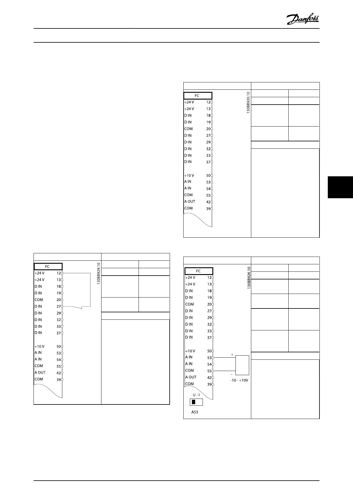
6.2 Application Examples
Parameters
Function Setting
1-29 Automatic
Motor Adaptation
(AMA)
[1] Enable
complete
AMA
5-12 Terminal 27
Digital Input
[2]* Coast
inverse
* = Default Value
Notes/comments: Parameter
group 1-2* must be set
according to motor
Table 6.1 AMA with T27 Connected
Parameters
Function Setting
1-29 Automatic
Motor Adaptation
(AMA)
[1] Enable
complete
AMA
5-12 Terminal 27
Digital Input
[0] No
operation
* = Default Value
Notes/comments: Parameter
group 1-2* must be set
according to motor
Table 6.2 AMA without T27 Connected
Parameters
Function Setting
6-10 Terminal 53
Low Voltage 0.07V*
6-11 Terminal 53
High Voltage
10V*
6-14 Terminal 53
Low Ref./Feedb.
Value
0RPM
6-15 Terminal 53
High Ref./Feedb.
Value
1500RPM
* = Default Value
Notes/comments:
Table 6.3 Analog Speed Reference (Voltage)
Application Set-Up Examples
VLT
®
AutomationDrive Operating
Instructions
MG.33.AJ.02 - VLT
®
is a registered Danfoss trademark 41
6

 Loading...


