Parameters
Function Setting
6-12 Terminal 53
Low Current
4mA*
6-13 Terminal 53
High Current
20mA*
6-14 Terminal 53
Low Ref./Feedb.
Value
0RPM
6-15 Terminal 53
High Ref./Feedb.
Value
1500RPM
* = Default Value
Notes/comments:
Table 6.4 Analog Speed Reference (Current)
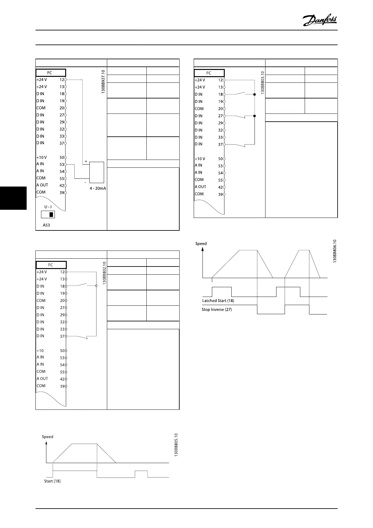
Parameters
Function Setting
5-10 Terminal 18
Digital Input
[8] Start*
5-12 Terminal 27
Digital Input
[0] No
operation
5-19 Terminal 37
Safe Stop
[1] Safe Stop
Alarm
* = Default Value
Notes/comments:
If 5-12 Terminal 27 Digital Input is
set to [0] No operation, a jumper
wire to terminal 27 is not
needed.
Table 6.5 Start/Stop Command with Safe Stop
Parameters
Function Setting
5-10 Terminal 18
Digital Input
[9] Latched
Start
5-12 Terminal 27
Digital Input
[6] Stop
Inverse
* = Default Value
Notes/comments:
If 5-12 Terminal 27 Digital Input is
set to [0] No operation, a jumper
wire to terminal 27 is not
needed.
Table 6.6 Pulse Start/Stop
Application Set-Up Examples
VLT
®
AutomationDrive Operating
Instructions
42 MG.33.AJ.02 - VLT
®
is a registered Danfoss trademark
6
 Loading...


