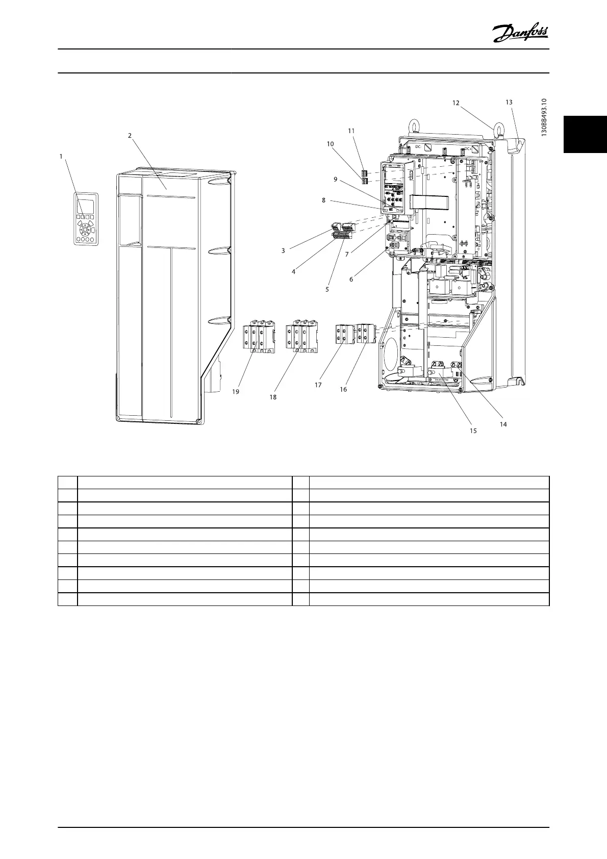
Illustration 1.2 Exploded View B and C Sizes, IP55/66
1 LCP 11 Relay 2 (04, 05, 06)
2Cover 12Lifting ring
3 RS-485 serial bus connector 13 Mounting slot
4 Digital I/O and 24 V power supply 14 Grounding clamp (PE)
5 Analog I/O connector 15 Cable strain relief / PE ground
6 Cable strain relief / PE ground 16 Brake terminal (-81, +82)
7 USB connector 17 Load sharing terminal (DC bus) (-88, +89)
8 Serial bus terminal switch 18 Motor output terminals 96 (U), 97 (V), 98 (W)
9 Analog switches (A53), (A54) 19 Mains input terminals 91 (L1), 92 (L2), 93 (L3)
10 Relay 1 (01, 02, 03)
1.1 Purpose of the Manual
This manual is intended to provide detailed information for
the installation and start up of the frequency converter.
Chapter 2 Installation provides requirements for mechanical
and electrical installation, including input, motor, control and
serial communications wiring, and control terminal
functions. Chapter 3 Start Up and Functional Testing provides
detailed procedures for start up, basic operational
programming, and functional testing. The remaining
chapters provide supplementary details. These include user
interface, detailed programming, application examples, start-
up troubleshooting, and specifications.
1.2 Additional Resources
Other resources are available to understand advanced
frequency converter functions and programming.
•
The Programming Guide provides greater detail in
how to work with parameters and many
application examples.
•
The Design Guide is intended to provide detailed
capabilities and functionality to design motor
control systems.
Introduction
VLT
®
AutomationDrive Operating
Instructions
MG.33.AJ.02 - VLT
®
is a registered Danfoss trademark 5
1 1