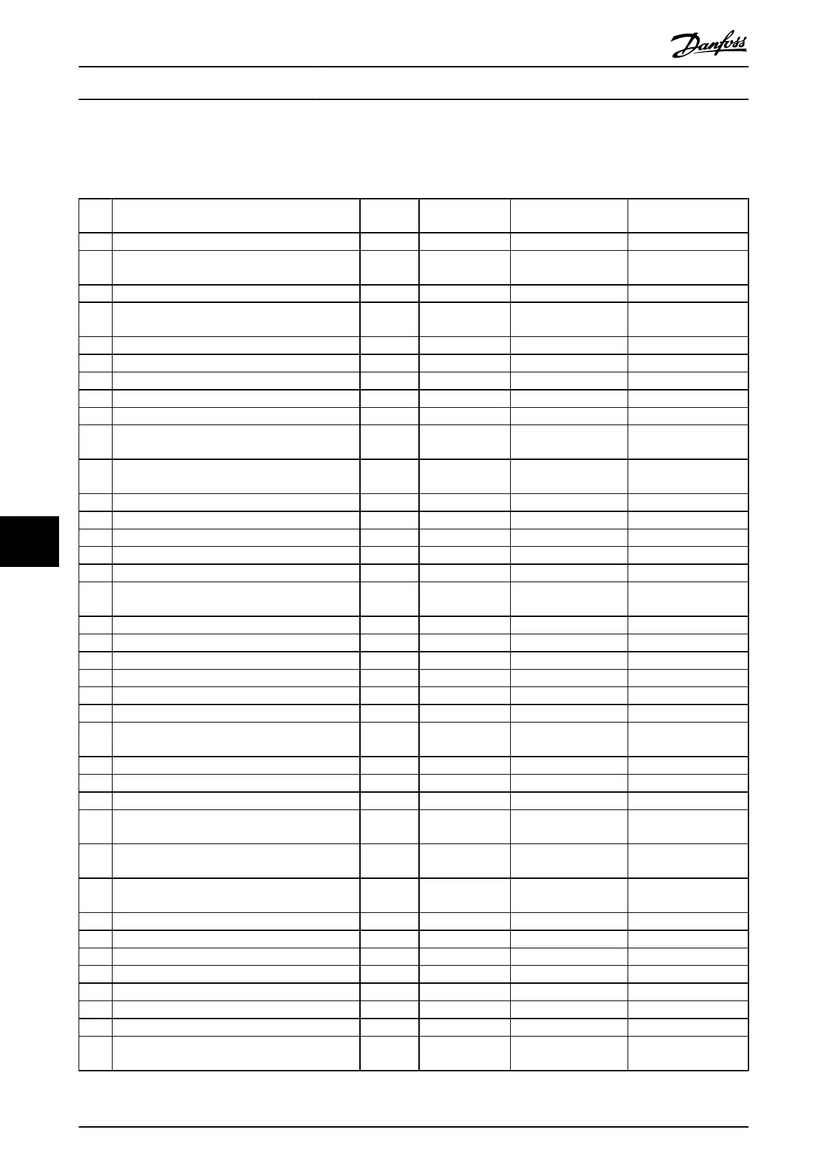
8.4 Warning and Alarm Definitions
defines whether a warning is issued prior to an alarm, and whether the alarm trips the unit or trip locks the unit.
No. Description Warning Alarm/Trip Alarm/Trip Lock Parameter
Reference
1 10 Volts low X
2 Live zero error (X) (X) 6-01 Live Zero Timeout
Function
3 No motor (X) 1-80 Function at Stop
4 Mains phase loss (X) (X) (X) 14-12 Function at Mains
Imbalance
5 DC link voltage high X
6 DC link voltage low X
7 DC over-voltage X X
8 DC under voltage X X
9 Inverter overloaded X X
10 Motor ETR over temperature (X) (X) 1-90 Motor Thermal
Protection
11 Motor thermistor over temperature (X) (X) 1-90 Motor Thermal
Protection
12 Torque limit X X
13 Over Current X X X
14 Earth Fault X X X
15 Hardware mismatch X X
16 Short Circuit X X
17 Control word time-out (X) (X) 8-04 Control Word
Timeout Function
20 Temp. Input Error
21 Param Error
22 Hoist Mech. Brake (X) (X) Parameter group 2-2*
23 Internal Fans X
24 External Fans X
25 Brake resistor short-circuited X
26 Brake resistor power limit (X) (X) 2-13 Brake Power
Monitoring
27 Brake chopper short-circuited X X
28 Brake check (X) (X) 2-15 Brake Check
29 Heatsink temp X X X
30 Motor phase U missing (X) (X) (X) 4-58 Missing Motor
Phase Function
31 Motor phase V missing (X) (X) (X) 4-58 Missing Motor
Phase Function
32 Motor phase W missing (X) (X) (X) 4-58 Missing Motor
Phase Function
33 Inrush Fault X X
34 Fieldbus communication fault X X
35 Option Fault
36 Mains failure X X
37 Phase imbalance X
38 Internal Fault X X
39 Heatsink sensor X X
40 Overload of Digital Output Terminal 27 (X) 5-00 Digital I/O Mode,
5-01 Terminal 27 Mode
Warnings and Alarms
VLT
®
AutomationDrive Operating
Instructions
50 MG.33.AJ.02 - VLT
®
is a registered Danfoss trademark
8
 Loading...


