3.5 Check Motor Rotation
Prior to running the frequency converter, check the motor
rotation.
1. Press [Hands on].
2. Press [►] for positive speed reference.
3. Check that the speed displayed is positive.
When 1-06 Clockwise Direction is set to [0]* Normal (default
clockwise):
4a. Verify that the motor turns clockwise.
5a. Verify that the LCP direction arrow is clockwise.
When 1-06 Clockwise Direction is set to [1] Inverse (counter-
clockwise):
4b. Verify that the motor turns counter-clockwise.
5b. Verify that the LCP direction arrow is counter-
clockwise.
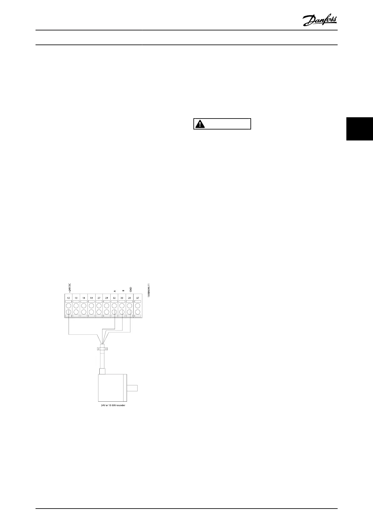
3.6 Check Encoder Rotation
Check encoder rotation only if encoder feedback is used.
Check encoder rotation in default open loop control.
1. Verify that the encoder connection is according to
the wiring diagram:
NOTE
When using an encoder option, refer to the option manual
2. Enter the Speed PID feed-back source in 7-00 Speed
PID Feedback Source.
3. Press [Hand On]
4.
Press [►] for positive speed reference
(1-06 Clockwise Direction at [0]* Normal).
5. Check in 16-57 Feedback [RPM] that the feed-back is
positive
NOTE
If the feedback is negative, the encoder connection is wrong!
3.7 Local-control Test
CAUTION
MOTOR START!
Ensure that the motor, system, and any attached equipment
is ready for start. It is the responsibility of the user to ensure
safe operation under any operational condition. Failure to
ensure that the motor, system, and any attached equipment
is ready for start could result in personal injury or equipment
damage.
NOTE
The hand on key on the LCP provides a local start command
to the frequency converter. The OFF key provides the stop
function.
When operating in local mode, the up and down arrows on
the LCP increase and decrease the speed output of the
frequency converter. The left and right arrow keys move the
display cursor in the numeric display.
1. Press [Hand On].
2.
Accelerate the frequency converter by pressing [
▲
]
to full speed. Moving the cursor left of the decimal
point provides quicker input changes.
3. Note any acceleration problems.
4. Press [OFF].
5. Note any deceleration problems.
If acceleration problems were encountered
•
If warnings or alarms occur, see 8 Warnings and
Alarms
•
Check that motor data is entered correctly
•
Increase the ramp-up time in 3-41 Ramp 1 Ramp Up
Time
•
Increase current limit in 4-18 Current Limit
•
Increase torque limit in 4-16 Torque Limit Motor
Mode
If deceleration problems were encountered
•
If warnings or alarms occur, see 8 Warnings and
Alarms
•
Check that motor data is entered correctly
•
Increase the ramp-down time in 3-42 Ramp 1 Ramp
Down Time
Start Up and Functional Tes...
VLT
®
AutomationDrive Operating
Instructions
MG.33.AJ.02 - VLT
®
is a registered Danfoss trademark 25
3