Frame size Bussmann PN* Rating Alternative Fuses
F LPJ-30 SP or SPI 30 A, 600 V Any listed Class J Dual Element, Time
Delay, 30 A
Table 5.19: 30 A Fuse Protected Terminal Fuse
Frame size
Bussmann PN* Rating Alternative Fuses
F LPJ-6 SP or SPI 6 A, 600 V Any listed Class J Dual Element, Time
Delay, 6 A
Table 5.20: Control Transformer Fuse
Frame size
Bussmann PN* Rating
F GMC-800MA 800 mA, 250 V
Table 5.21: NAMUR Fuse
Frame size
Bussmann PN* Rating Alternative Fuses
F LP-CC-6 6 A, 600 V Any listed Class CC, 6 A
Table 5.22: Safety Relay Coil Fuse with PILS Relay
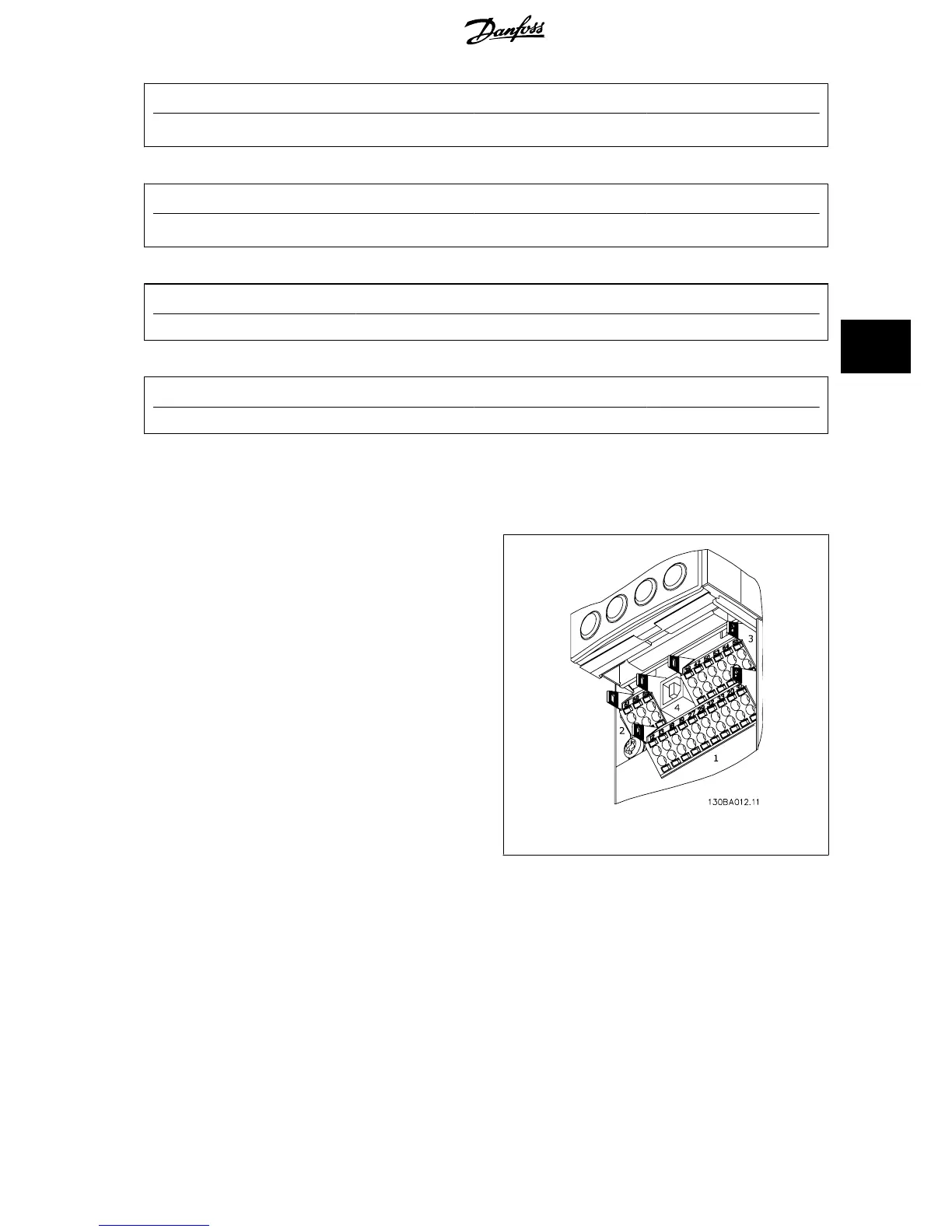
5.2.9 Control Terminals
Drawing reference numbers:
1. 10 pole plug digital I/O.
2. 3 pole plug RS485 Bus.
3. 6 pole analog I/O.
4. USB Connection.
Illustration 5.18: Control terminals (all enclosures)
5.2.10 Control Cable Terminals
To mount the cable to the terminal:
1. Strip isolation of 9-10 mm
2.
Insert a screw driver
1)
in the rectangular hole.
3. Insert the cable in the adjacent circular hole.
4. Remove the screw driver. The cable is now mounted to the ter-
minal.
To remove the cable from the terminal:
1.
Insert a screw driver
1)
in the square hole.
2. Pull out the cable.
1)
Max. 0.4 x 2.5 mm
VLT
®
HVAC Drive Design Guide 5 How to Install
MG.11.B9.02 - VLT
®
is a registered Danfoss trademark
101
5

 Loading...


