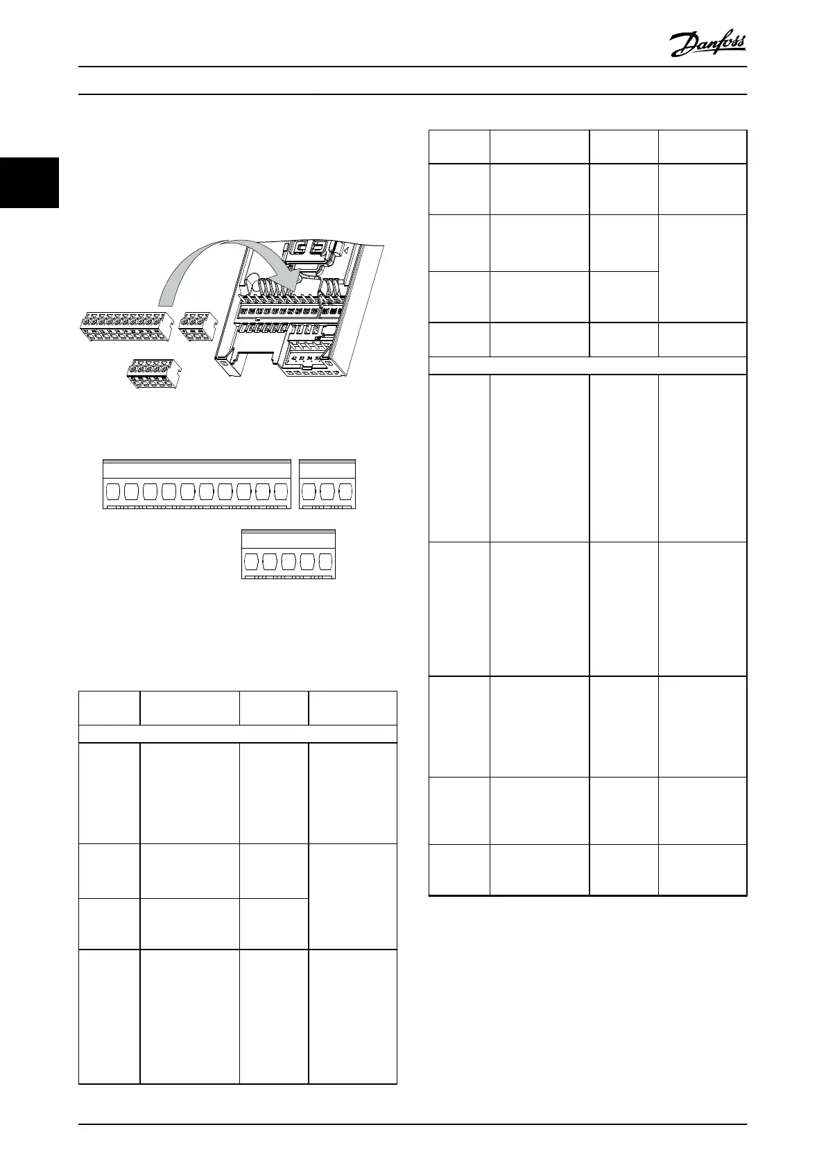
2.2.3 Control Terminal Types
Illustration 2.7 shows the removable frequency converter
connectors. Terminal functions and default settings are
summarized in Table 2.2 and Table 2.3.
Illustration 2.7 Control Terminal Locations
130BE214.10
37 38 12 13 18 19 27 29 32 33 61
42 53 54 50 55
68 69
1
3
2
Illustration 2.8 Terminal Numbers
See chapter 7.6 Control Input/Output and Control Data for
terminal ratings details.
Terminal Parameter
Default
setting
Description
Digital I/O, pulse I/O, encoder
12, 13 – +24 V DC
24 V DC supply
voltage.
Maximum
output current is
100 mA for all
24 V loads.
18
Parameter 5-10 Ter
minal 18 Digital
Input
[8] Start
Digital inputs.
19
Parameter 5-11 Ter
minal 19 Digital
Input
[10]
Reversing
27
Parameter 5-01 Ter
minal 27 Mode
Parameter 5-12 Ter
minal 27 Digital
Input
Parameter 5-30 Ter
minal 27 Digital
Output
DI [2] Coast
inverse
DO [0] No
operation
Selectable for
either digital
input, digital
output, or pulse
output. The
default setting is
digital input.
Terminal Parameter
Default
setting
Description
29
Parameter 5-13 Ter
minal 29 Digital
Input
[14] Jog Digital input.
32
Parameter 5-14 Ter
minal 32 Digital
Input
[0] No
operation
Digital input,
24 V encoder.
Terminal 33 can
be used for
pulse input.
33
Parameter 5-15 Ter
minal 33 Digital
Input
[0] No
operation
37, 38 – STO
Functional safety
inputs.
Analog inputs/outputs
42
Parameter 6-91 Ter
minal 42 Analog
Output
[0] No
operation
Programmable
analog output.
The analog
signal is 0–
20 mA or 4–
20 mA at a
maximum of
500 Ω. Can also
be congured as
digital outputs.
50 – +10 V DC
10 V DC analog
supply voltage.
15 mA
maximum
commonly used
for potenti-
ometer or
thermistor.
53
Parameter group
6-1* Analog input
53
–
Analog input.
Only voltage
mode is
supported. It can
also be used as
digital input.
54
Parameter group
6-2* Analog input
54
–
Analog input.
Selectable
between voltage
or current mode.
55 – –
Common for
digital and
analog inputs.
Table 2.2 Terminal Descriptions - Digital Inputs/Outputs,
Analog Inputs/Outputs
Product Overview
VLT
®
Midi Drive FC 280
16 Danfoss A/S © 03/2016 All rights reserved. MG07B102
22

 Loading...


