3 Application Examples
3.1 Introduction
3.1.1 Encoder Connection
The purpose of this guideline is to ease the set-up of
encoder connection to the frequency converter. Before
setting up the encoder, the basic settings for a closed-loop
speed control system are shown.
130BE805.10
+24 V DC
+24 V DC
A
B
Z
GND
12 13 18 19 3227 29 33 55
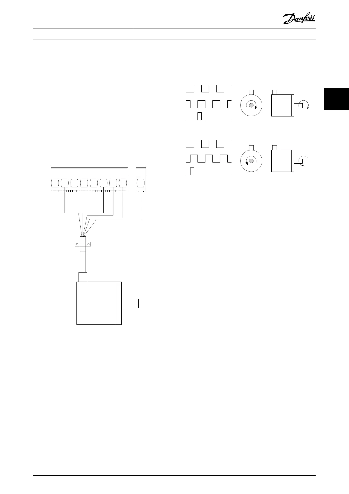
Illustration 3.1 24 V Encoder
Illustration 3.2 24 V Incremental Encoder, Maximum Cable
Length 5 m (16.4 ft)
3.1.2 Encoder Direction
The order in which the pulses enter the frequency
converter determines the direction of the encoder.
Clockwise direction means that channel A is 90 electrical
degrees before channel B.
Counterclockwise direction means that channel B is 90
electrical degrees before A.
The direction is determined by looking into the shaft end.
3.1.3 Closed-loop Drive System
A drive system usually consists of more elements such as:
•
Motor.
•
Brake (gearbox, mechanical brake).
•
Frequency converter.
•
Encoder as feedback system.
•
Brake resistor for dynamic brake.
•
Transmission.
•
Load.
Applications demanding mechanical brake control usually
need a brake resistor.
Application Examples Design Guide
MG07B102 Danfoss A/S © 03/2016 All rights reserved. 45
3 3

 Loading...


