2.6.3 EMC Immunity Requirements
The immunity requirements for frequency converters depend on the environment in which they are installed. The
requirements for the industrial environment are higher than the requirements for the home and oce environment. All
Danfoss frequency converters comply with the requirements for the industrial environment. Therefore, they also comply with
the lower requirements for home and oce environment with a large safety margin.
To document immunity against burst transient from electrical phenomena, the following immunity tests have been made on
a system consisting of:
•
A frequency converter (with options if relevant)
•
A shielded control cable
•
A control box with potentiometer, motor cable, and motor.
The tests were performed in accordance with the following basic standards:
•
EN 61000-4-2 (IEC 61000-4-2) Electrostatic discharges (ESD): Simulation of electrostatic discharges from human
beings.
•
EN 61000-4-3 (IEC 61000-4-3) Radiated immunity: Amplitude modulated simulation of the
eects of radar and
radio communication equipment and mobile communications equipment.
•
EN 61000-4-4 (IEC 61000-4-4) Burst transients: Simulation of interference caused by switching a contactor, relay,
or similar devices.
•
EN 61000-4-5 (IEC 61000-4-5) Surge transients: Simulation of transients caused by, for example, lightning that
strikes near installations.
•
EN 61000-4-6 (IEC 61000-4-6) Conducted immunity: Simulation of the
eect from radio-transmission equipment
joined by connection cables.
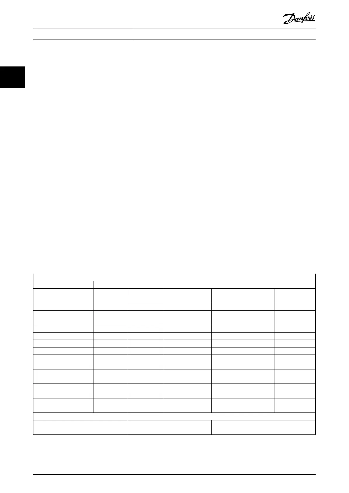
The immunity requirements should follow product standard IEC 61800-3 and Danfoss internal standards. See Table 2.13 for
details.
Voltage range: 380–480 V
Product standard 61800-3
Test
ESD Radiated
immunity
Burst Surge Conducted
immunity
Acceptance criterion B B B A A
Mains cable – – 2 kV CN
2 kV/2 Ω DM
2 kV/12 Ω CM
10 V
RMS
Motor cable – – 4 kV CCC – 10 V
RMS
Brake cable – – 4 kV CCC – 10 V
RMS
Load sharing cable – – 4 kV CCC – 10 V
RMS
Relay cable – – 4 kV CCC – 10 V
RMS
Control cable – –
Length >2 m (6.6 ft)
1 kV CCC
Unshielded:
1 kV/42 Ω CM
10 V
RMS
Standard/eldbus cable – –
Length >2 m (6.6 ft)
1 kV CCC
Unshielded:
1 kV/42 Ω CM
10 V
RMS
LCP cable – –
Length >2 m (6.6 ft)
1 kV CCC
– 10 V
RMS
Enclosure
4 kV CD
8 kV AD
10 V/m – – –
Denitions
CD: Contact discharge
AD: Air discharge
DM: Dierential mode
CM: Common mode
CN: Direct injection through coupling network
CCC: Injection through capacitive coupling clamp
Table 2.13 EMC Immunity Requirements
Product Overview
VLT
®
Midi Drive FC 280
38 Danfoss A/S © 03/2016 All rights reserved. MG07B102
22

 Loading...


