2.9.2 Dynamic Braking
Dynamic braking is established by:
•
Resistor brake: A brake IGBT keeps the
overvoltage under a certain threshold by
directing the brake energy from the motor to the
connected brake resistor (parameter 2-10 Brake
Function = [1] Resistor brake).
Adjust the threshold in parameter 2-14 Brake
voltage reduce, with 70 V range for 3x380–480 V.
•
AC brake: The brake energy is distributed in the
motor by changing the loss conditions in the
motor. The AC brake function cannot be used in
applications with high cycling frequency as this
overheats the motor (parameter 2-10 Brake
Function = [2] AC brake).
•
DC brake: An overmodulated DC current added to
the AC current works as an eddy current brake
(parameter 2-02 DC Braking Time≠0 s).
2.9.3 Brake Resistor Selection
To handle higher demands by generatoric braking, a brake
resistor is necessary. Using a brake resistor ensures that the
heat is absorbed in the brake resistor and not in the
frequency converter. For more information, see the VLT
®
Brake Resistor MCE 101 Design Guide.
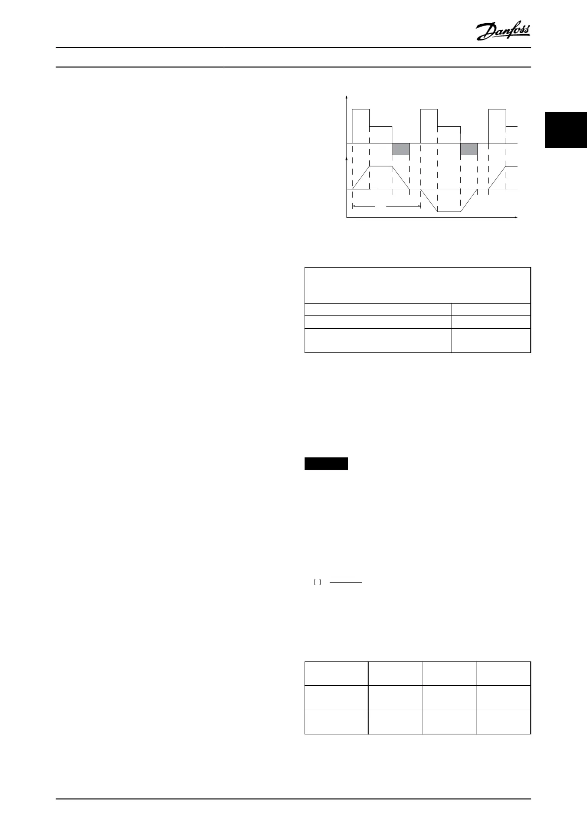
If the amount of kinetic energy transferred to the resistor
in each braking period is not known, calculate the average
power based on the cycle time and braking time. The
resistor intermittent duty cycle is an indication of the duty
cycle at which the resistor is active. Illustration 2.32 shows a
typical braking cycle.
The intermittent duty cycle for the resistor is calculated as
follows:
Duty cycle = t
b
/T
t
b
is the braking time in seconds.
T = cycle time in seconds.
T
ta
tc
tb
to ta
tc
tb
to ta
130BA167.10
Load
Time
Speed
Illustration 2.32 Typical Braking Cycle
Power range:
0.37–22 kW (0.5–30 hp) 3x380–480 V
0.37–3.7 kW (0.5–5 hp) 3x200–240 V
Cycle time (s) 120
Braking duty cycle at 100% torque Continuous
Braking duty cycle at overtorque
(150/160%)
40%
Table 2.14 Braking at High Overload Torque Level
Danfoss oers brake resistors with duty cycles of 10% and
40%. If a 10% duty cycle is applied, the brake resistors are
able to absorb brake power for 10% of the cycle time. The
remaining 90% of the cycle time is used for dissipating
excess heat.
NOTICE
Make sure that the resistor is designed to handle the
required braking time.
The maximum allowed load on the brake resistor is stated
as a peak power at a given intermittent duty cycle and can
be calculated as:
Brake resistance calculation
R
br
Ω =
U
dc,br
2
x0 . 83
P
peak
where
P
peak
= P
motor
x M
br
[%] x η
motor
x η
VLT
[W]
As shown, the brake resistance depends on the DC-link
voltage (U
dc
).
Size Brake active
U
dc,br
Warning
before cutout
Cutout (trip)
FC 280
3x380–480 V
770 V 800 V 800 V
FC 280
3x200–240 V
390 V 410 V 410 V
Table 2.15 Threshold of the Brake Resistance
Product Overview Design Guide
MG07B102 Danfoss A/S © 03/2016 All rights reserved. 41
2 2

 Loading...


