5.8.6 Data Field
The data eld is constructed using sets of 2 hexadecimal
digits, in the range of 00–FF hexadecimal. These digits are
made up of 1 RTU character. The data eld of telegrams
sent from a master to a slave device contains additional
information which the slave must use to perform
accordingly.
The information can include items such as:
•
Coil or register addresses.
•
The quantity of items to be handled.
•
The count of actual data bytes in the
eld.
5.8.7 CRC Check Field
Telegrams include an error-checking eld, operating based
on a cyclic redundancy check (CRC) method. The CRC eld
checks the contents of the entire telegram. It is applied
regardless of any parity check method used for the
individual characters of the telegram. The transmitting
device calculates the CRC value and appends the CRC as
the last eld in the telegram. The receiving device
recalculates a CRC during receipt of the telegram and
compares the calculated value to the actual value received
in the CRC eld. 2 unequal values result in bus timeout.
The error-checking eld contains a 16-bit binary value
implemented as 2 8-bit bytes. After the implementation,
the low-order byte of the eld is appended rst, followed
by the high-order byte. The CRC high-order byte is the last
byte sent in the telegram.
5.8.8 Coil Register Addressing
In Modbus, all data is organized in coils and holding
registers. Coils hold a single bit, whereas holding registers
hold a 2 byte word (that is 16 bits). All data addresses in
Modbus telegrams are referenced to 0. The rst occurrence
of a data item is addressed as item number 0. For example:
The coil known as coil 1 in a programmable controller is
addressed as coil 0000 in the data address eld of a
Modbus telegram. Coil 127 decimal is addressed as coil
007Ehex (126 decimal).
Holding register 40001 is addressed as register 0000 in the
data address eld of the telegram. The function code eld
already species a holding register operation. Therefore,
the 4XXXX reference is implicit. Holding register 40108 is
addressed as register 006Bhex (107 decimal).
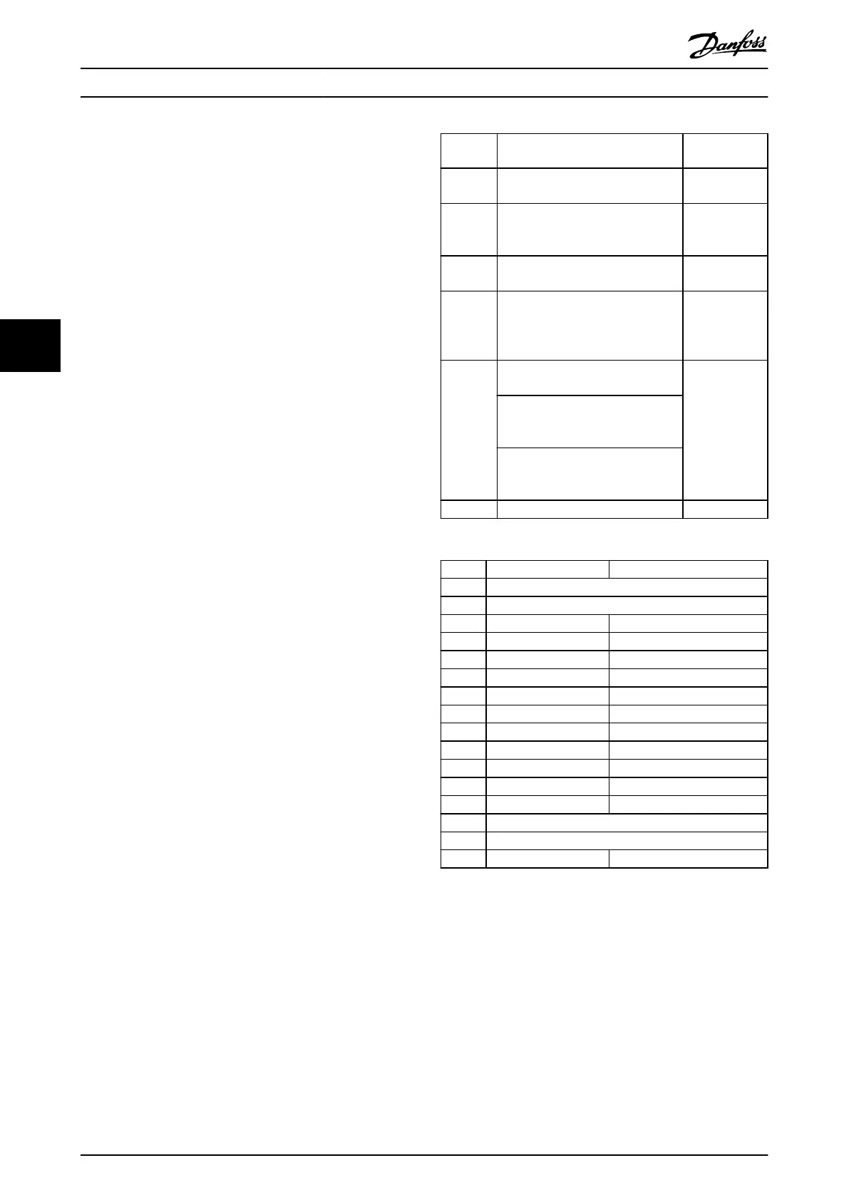
Coil
number
Description Signal
direction
1–16 Frequency converter control word
(see Table 5.16).
Master to slave
17–32 Frequency converter speed or
setpoint reference range 0x0–
0xFFFF (-200% ... ~200%).
Master to slave
33–48 Frequency converter status word
(see Table 5.17).
Slave to master
49–64 Open-loop mode: Frequency
converter output frequency.
Closed-loop mode: Frequency
converter feedback signal.
Slave to master
65
Parameter write control (master to
slave).
Master to slave
0 = Parameter changes are written
to the RAM of the frequency
converter.
1 = Parameter changes are written
to the RAM and EEPROM of the
frequency converter.
66–65536 Reserved. –
Table 5.15 Coil Register
Coil 0 1
01 Preset reference lsb
02 Preset reference msb
03 DC brake No DC brake
04 Coast stop No coast stop
05 Quick stop No quick stop
06 Freeze frequency No freeze frequency
07 Ramp stop Start
08 No reset Reset
09 No jog Jog
10 Ramp 1 Ramp 2
11 Data not valid Data valid
12 Relay 1 o Relay 1 on
13 Relay 2 o Relay 2 on
14 Set up lsb
15 –
16 No reversing Reversing
Table 5.16 Frequency Converter Control Word (FC Prole)
RS485 Installation and Set-...
VLT
®
Midi Drive FC 280
62 Danfoss A/S © 03/2016 All rights reserved. MG07B102
55

 Loading...


