The endpoints P1 and P2 are dened in Table 2.4 depending on the choice of input.
Input Analog 53
voltage mode
Analog 54
voltage mode
Analog 54
current mode
Pulse Input 29 Pulse Input 33
P1=(Minimum input value, minimum reference value)
Minimum reference value Parameter 6-14 Te
rminal 53 Low
Ref./Feedb. Value
Parameter 6-24 Te
rminal 54 Low
Ref./Feedb. Value
Parameter 6-24 Ter
minal 54 Low Ref./
Feedb. Value
Parameter 5-52 Ter
m. 29 Low Ref./
Feedb. Value
Parameter 5-57 Term. 33
Low Ref./Feedb. Value
Minimum input value Parameter 6-10 Te
rminal 53 Low
Voltage [V]
Parameter 6-20 Te
rminal 54 Low
Voltage [V]
Parameter 6-22 Ter
minal 54 Low
Current [mA]
Parameter 5-50 Ter
m. 29 Low
Frequency [Hz]
Parameter 5-55 Term. 33
Low Frequency [Hz]
P2=(Maximum input value, maximum reference value)
Maximum reference value Parameter 6-15 Te
rminal 53 High
Ref./Feedb. Value
Parameter 6-25 Te
rminal 54 High
Ref./Feedb. Value
Parameter 6-25 Ter
minal 54 High Ref./
Feedb. Value
Parameter 5-53 Ter
m. 29 High Ref./
Feedb. Value
Parameter 5-58 Term. 33
High Ref./Feedb. Value
Maximum input value Parameter 6-11 Te
rminal 53 High
Voltage [V]
Parameter 6-21 Te
rminal 54 High
Voltage [V]
Parameter 6-23 Ter
minal 54 High
Current [mA]
Parameter 5-51 Ter
m. 29 High
Frequency [Hz]
Parameter 5-56 Term. 33
High Frequency [Hz]
Table 2.4 P1 and P2 Endpoints
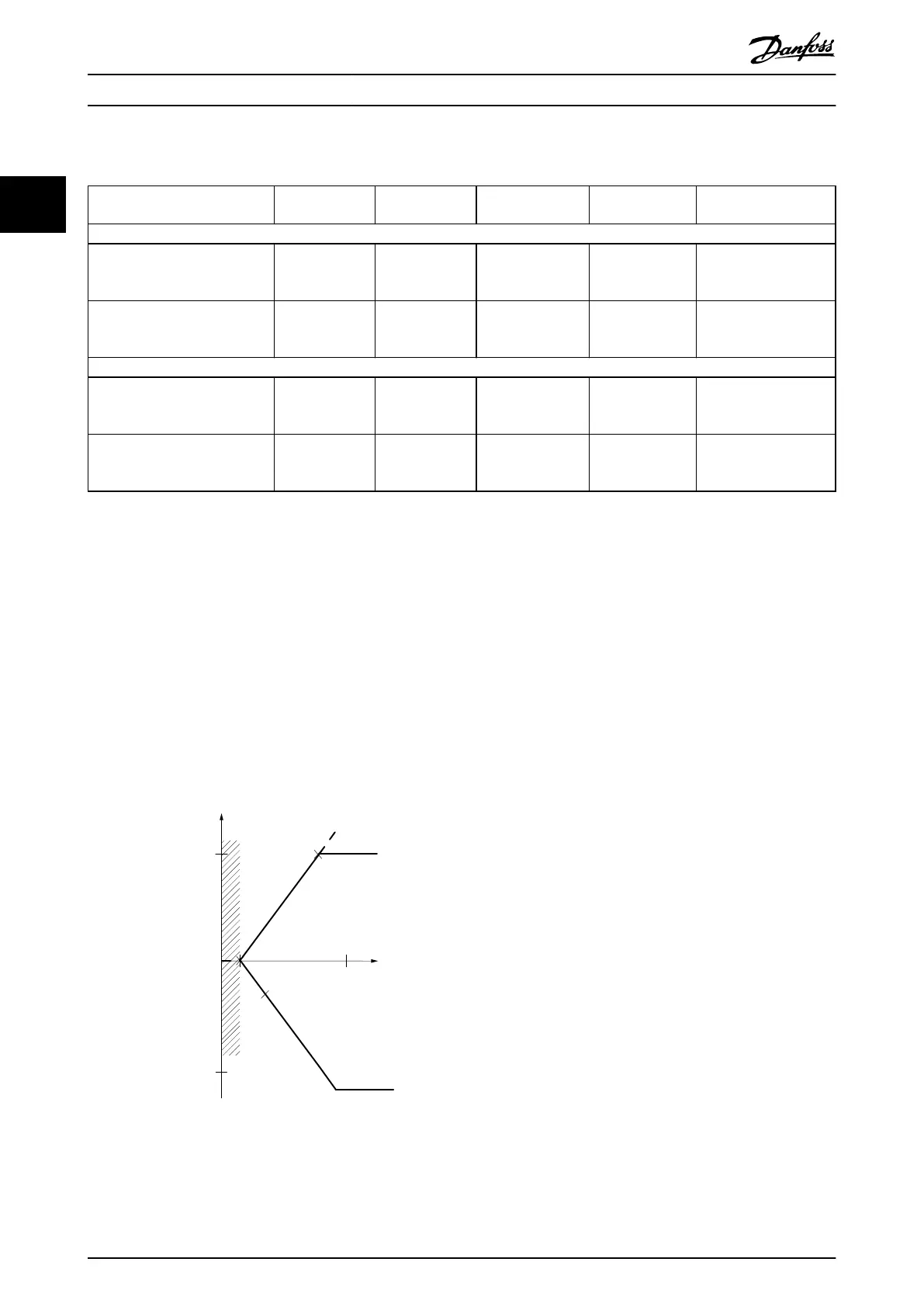
2.4.4 Dead Band Around Zero
Sometimes, the reference (in rare cases also the feedback) should have a dead band around 0 to ensure that the machine is
stopped when the reference is near 0.
To make the dead band active and to set the amount of dead band, do the following:
•
Set either the minimum reference value (see Table 2.4 for relevant parameter) or maximum reference value at 0. In
other words, either P1 or P2 must be on the X-axis in Illustration 2.18.
•
Ensure that both points dening the scaling graph are in the same quadrant.
P1 or P2
denes the size of the dead band as shown in Illustration 2.18.
[Hz] or “No unit”
Resource input
[mA]
Quadrant 2
Low reference/feedback
value
High reference/feedback
value
1
-50
16
50
20
P1
P2
0
forward
reverse
Terminal low
Illustration 2.18 Size of Dead Band
Case 1: Positive reference with dead band, digital input to trigger reverse, part I
Illustration 2.19 shows how reference input with limits inside minimum to maximum limits clamps.
Product Overview
VLT
®
Midi Drive FC 280
24 Danfoss A/S © 03/2016 All rights reserved. MG07B102
22

 Loading...


