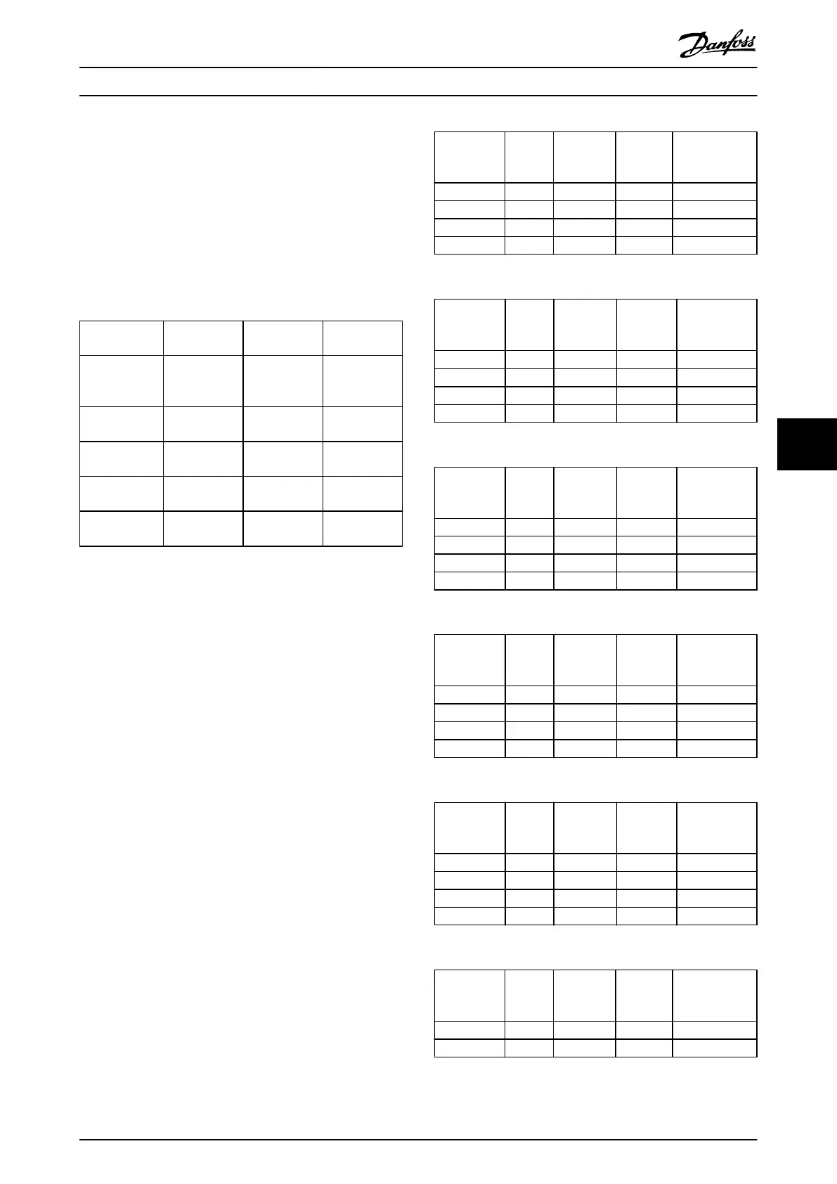
7.10 Acoustic Noise
The acoustic noise from the frequency converter comes
from 3 sources:
•
DC intermediate circuit coils.
•
Integral fan.
•
RFI lter choke.
The typical values measured at a distance of 1 m (3.3 ft)
from the unit:
Enclosure size
[kW (hp)]
80% fan
speed [dBA]
Full fan speed
[dBA]
Background
noise
K1
0.37–2.2
(0.5–3.0)
41.4 42.7 33
K2
3.0–5.5 (4.0–7.5)
50.3 54.3 32.9
K3
7.5 (10)
51 54.2 33
K4
11–15 (15–20)
59 61.1 32.9
K5
18.5–22 (25–30)
64.6 65.6 32.9
Table 7.5 Typical Measured Values
7.11
dU/dt Conditions
When a transistor in the frequency converter bridge
switches, the voltage across the motor increases by a
dU/dt ratio depending on the following factors:
•
The motor cable type.
•
The cross-section of the motor cable.
•
The length of the motor cable.
•
Whether the motor cable is shielded or not.
•
Inductance.
The natural induction causes an overshoot U
PEAK
in the
motor voltage before it stabilizes itself at a level
depending on the voltage in the DC link. The rise time and
the peak voltage U
PEAK
aect the service life of the motor.
If the peak voltage is too high, motors without phase coil
insulation are aected. The longer the motor cable, the
higher the rise time and peak voltage.
Switching of the IGBTs cause peak voltage on the motor
terminals. The FC 280 complies with IEC 60034-25
regarding motors designed to be controlled by frequency
converters. The FC 280 also complies with IEC 60034-17
regarding Norm motors controlled by frequency converters.
The following dU/dt data are measured at the motor
terminal side:
Cable
length
[m (ft)]
Mains
voltage
[V]
Rise time
[μsec]
U
PEAK
[kV]
dU/dt
[kV/μsec]
5 (16.4) 400 0.0904 0.718 6.41
50 (164) 400 0.292 1.05 2.84
5 (16.4) 480 0.108 0.835 6.20
50 (164) 480 0.32 1.25 3.09
Table 7.6 dU/dt Data for FC 280, 2.2 kW (3.0 hp), 3x380–480 V
Cable
length
[m (ft)]
Mains
voltage
[V]
Rise time
[μsec]
U
PEAK
[kV]
dU/dt
[kV/μsec]
5 (16.4) 400 0.096 0.632 5.31
50 (164) 400 0.306 0.99 2.58
5 (16.4) 480 0.118 0.694 4.67
50 (164) 480 0.308 1.18 3.05
Table 7.7 dU/dt Data for FC 280, 5.5 kW (7.5 hp), 3x380–480 V
Cable
length
[m (ft)]
Mains
voltage
[V]
Rise time
[μsec]
U
PEAK
[kV]
dU/dt
[kV/μsec]
5 (16.4) 400 0.128 0.732 4.54
50 (164) 400 0.354 1.01 2.27
5 (16.4) 480 0.134 0.835 5.03
50 (164) 480 0.36 1.21 2.69
Table 7.8 dU/dt Data for FC 280, 7.5 kW (10 hp), 3x380–480 V
Cable
length
[m (ft)]
Mains
voltage
[V]
Rise time
[μsec]
U
PEAK
[kV]
dU/dt
[kV/μsec]
5 (16.4) 400 0.26 0.84 2.57
50 (164) 400 0.738 1.07 1.15
5 (16.4) 480 0.334 0.99 2.36
50 (164) 480 0.692 1.25 1.44
Table 7.9 dU/dt Data for FC 280, 15 kW (20 hp), 3x380–480 V
Cable
length
[m (ft)]
Mains
voltage
[V]
Rise time
[μsec]
U
PEAK
[kV]
dU/dt
[kV/μsec]
5 (16.4) 400 0.258 0.652 2.01
50 (164) 400 0.38 1.03 2.15
5 (16.4) 480 0.258 0.752 2.34
50 (164) 480 0.4 1.23 2.42
Table 7.10 dU/dt Data for FC 280, 22 kW (30 hp), 3x380–480 V
Cable
length
[m (ft)]
Mains
voltage
[V]
Rise time
[μsec]
U
PEAK
[kV]
dU/dt
[kV/μsec]
5 (16.4) 240 0.0712 0.484 5.44
50 (164) 240 0.224 0.594 2.11
Table 7.11 dU/dt Data for FC 280, 1.5 kW (2.0 hp), 3x200–240 V
Specications Design Guide
MG07B102 Danfoss A/S © 03/2016 All rights reserved. 83
7 7

 Loading...


