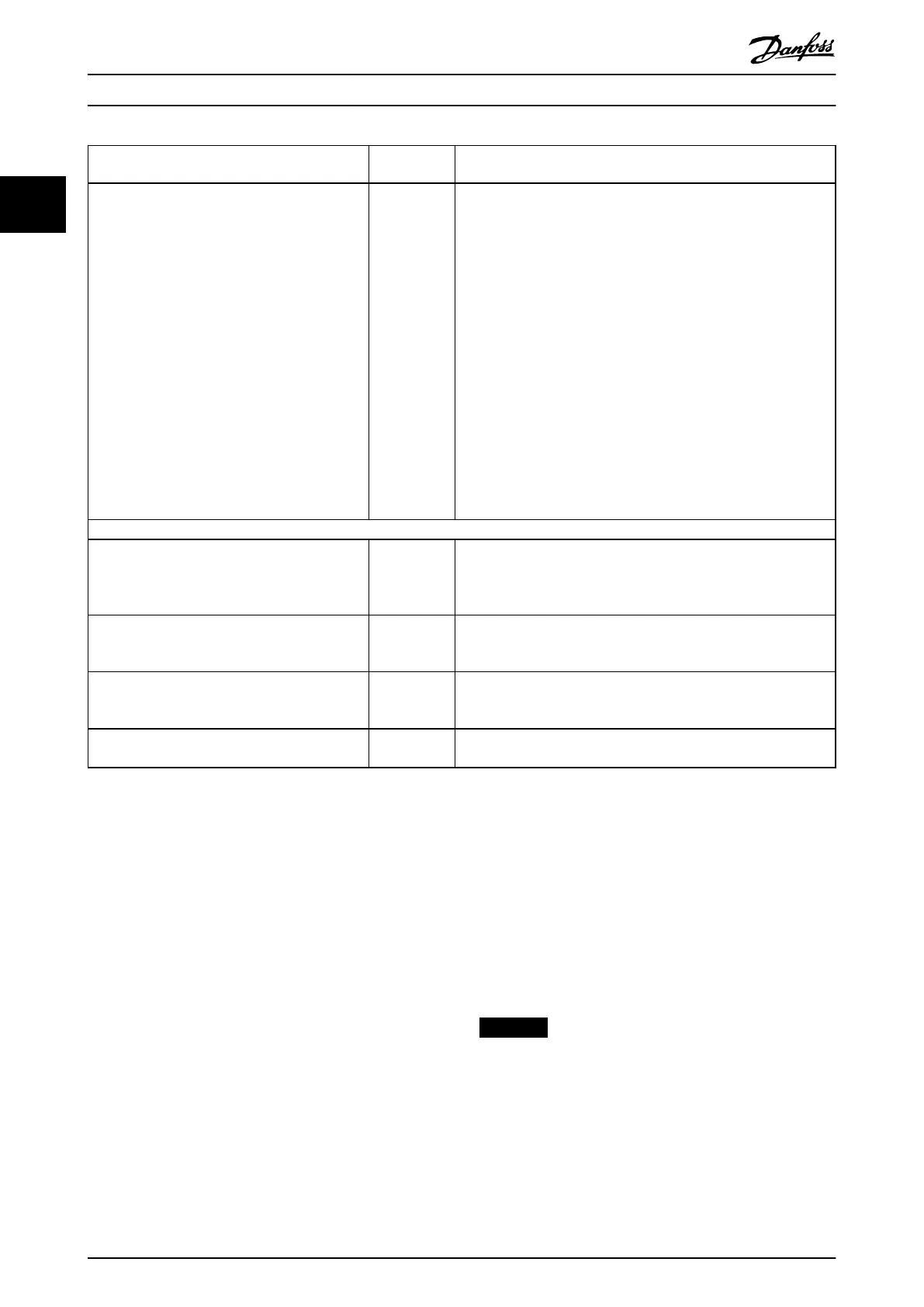
Function Parameter
number
Setting
Set terminal 53 low voltage.
Set terminal 53 high voltage.
Set terminal 54 low feedback value.
Set terminal 54 high feedback value.
Set feedback source.
Parameter 6-10
Terminal 53
Low Voltage
Parameter 6-11
Terminal 53
High Voltage
Parameter 6-24
Terminal 54
Low Ref./Feedb.
Value
Parameter 6-25
Terminal 54
High Ref./
Feedb. Value
Parameter 7-20
Process CL
Feedback 1
Resource
0 V
10 V
-5 °C (23 °F)
35 °C (95 °F)
[2] Analog input 54
6) Basic PID settings:
Process PID normal/inverse. Parameter 7-30
Process PID
Normal/
Inverse Control
[0] Normal
Process PID anti wind-up. Parameter 7-31
Process PID
Anti Windup
[1] On
Process PID start speed. Parameter 7-32
Process PID
Start Speed
300 RPM
Save parameters to LCP. Parameter 0-50
LCP Copy
[1] All to LCP
Table 2.10 Example of Process PID Control Set-up
2.5.5 Process Controller Optimization
After conguring the basic settings as described in
chapter 2.5.5 Programming Order, optimize the proportional
gain, the integration time, and the dierentiation time
(parameter 7-33 Process PID Proportional Gain,
parameter 7-34 Process PID Integral Time, and
parameter 7-35 Process PID Dierentiation Time). In most
processes, complete the following procedure:
1. Start the motor.
2. Set parameter 7-33 Process PID Proportional Gain
to 0.3 and increase it until the feedback signal
again begins to vary continuously. Reduce the
value until the feedback signal has stabilized.
Lower the proportional gain by 40–60%.
3. Set parameter 7-34 Process PID Integral Time to 20
s and reduce the value until the feedback signal
again begins to vary continuously. Increase the
integration time until the feedback signal
stabilizes, followed by an increase of 15–50%.
4. Only use parameter 7-35 Process PID Dierentiation
Time for fast-acting systems (dierentiation time).
The typical value is 4 times the set integration
time. Use the dierentiator when the setting of
the proportional gain and the integration time
has been fully optimized. Make sure that the
lowpass lter dampens the oscillations on the
feedback signal suciently.
NOTICE
If necessary, start/stop can be activated several times to
provoke a variation of the feedback signal.
Product Overview
VLT
®
Midi Drive FC 280
34 Danfoss A/S © 03/2016 All rights reserved. MG07B102
22

 Loading...


