5 RS485 Installation and Set-up
5.1 Introduction
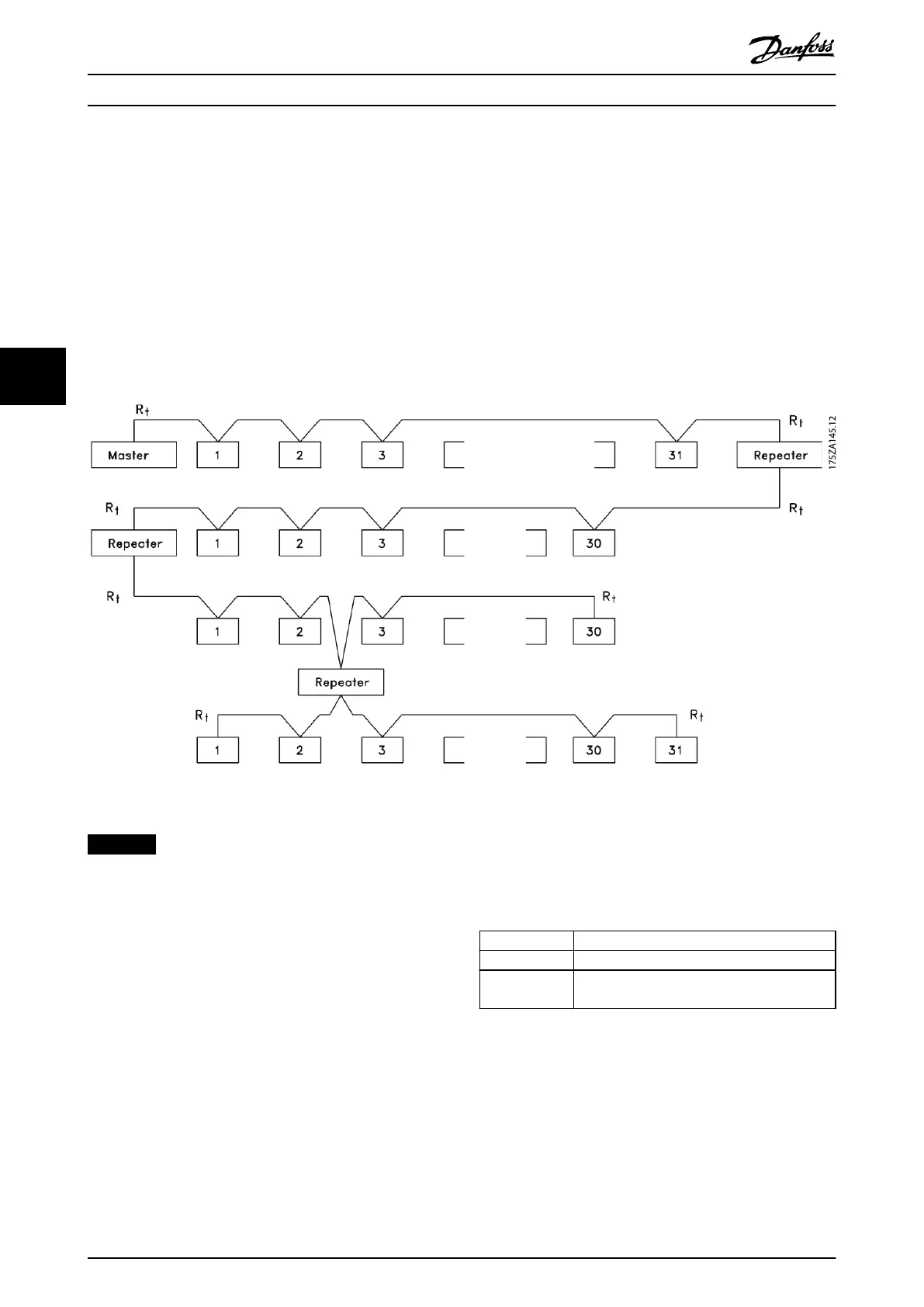
5.1.1 Overview
RS485 is a 2-wire bus interface compatible with multi-drop network topology. The nodes can be connected as a bus, or via
drop cables from a common trunk line. A total of 32 nodes can be connected to 1 network segment.
Repeaters divide network segments, see Illustration 5.1.
Illustration 5.1 RS485 Bus Interface
NOTICE
Each repeater functions as a node within the segment in
which it is installed. Each node connected within a given
network must have a unique node address across all
segments.
Terminate each segment at both ends, using either the
termination switch (S801) of the frequency converters or a
biased termination resistor network. Always use shielded
twisted pair (STP) cable for bus cabling and follow good
common installation practice.
Low-impedance ground connection of the shield at every
node is important, including at high frequencies. Thus,
connect a large surface of the shield to ground, for
example with a cable clamp or a conductive cable gland.
Sometimes, it is necessary to apply potential-equalizing
cables to maintain the same ground potential throughout
the network, particularly in installations with long cables.
To prevent impedance mismatch, use the same type of
cable throughout the entire network. When connecting a
motor to the frequency converter, always use shielded
motor cable.
Cable Shielded twisted pair (STP)
Impedance [Ω]
120
Cable length [m
(ft)]
Maximum 1200 (3937) (including drop lines).
Maximum 500 (1640) station-to-station.
Table 5.1 Cable Specications
5.1.2 Network Connection
Connect the frequency converter to the RS485 network as
follows (see also Illustration 5.2):
1. Connect signal wires to terminal 68 (P+) and
terminal 69 (N-) on the main control board of the
frequency converter.
2. Connect the cable shield to the cable clamps.
RS485 Installation and Set-...
VLT
®
Midi Drive FC 280
54 Danfoss A/S © 03/2016 All rights reserved. MG07B102
55

 Loading...


