2.7 Galvanic Isolation
PELV oers protection through extra low voltage.
Protection against electric shock is ensured when the
electrical supply is of the PELV type and the installation is
made as described in local/national regulations on PELV
supplies.
All control terminals and relay terminals 01–03 comply
with PELV (protective extra low voltage). This does not
apply to grounded Delta leg above 400 V.
Galvanic (ensured) isolation is obtained by fullling
requirements for higher isolation and by providing the
relevant creapage/clearance distances. These requirements
are described in the EN 61800-5-1 standard.
The components that make up the electrical isolation, as
shown in Illustration 2.27, also comply with the
requirements for higher isolation and the relevant test as
described in EN 61800-5-1.
The PELV galvanic isolation can be shown in 3 locations
(see Illustration 2.27):
To maintain PELV, all connections made to the control
terminals must be PELV, for example, the thermistor must
be reinforced/double insulated.
1 Power supply (SMPS) for control cassette
2 Communication between power card and control cassette
3 Isolation between STO inputs and IGBT circuit
4 Customer relay
Illustration 2.27 Galvanic Isolation
The functional galvanic isolation (a and b on
Illustration 2.27) is for the 24 V back-up option and the
RS485 standard bus interface.
WARNING
Before touching any electrical parts, ensure that other
voltage inputs have been disconnected, such as load
sharing (linkage of DC intermediate circuit) and the
motor connection for kinetic back-up. Observe the
discharge time stated in chapter Safety in the VLT
®
Midi
Drive FC 280 Operating Guide. Failure to follow
recommendations could result in death or serious injury.
2.8 Ground Leakage Current
Follow national and local codes regarding protective
grounding of equipment with a leakage current >3.5 mA.
Frequency converter technology implies high frequency
switching at high power. This switching generates a
leakage current in the ground connection. A fault current
in the frequency converter at the output power terminals
might contain a DC component, which can charge the
lter capacitors and cause a transient ground current.
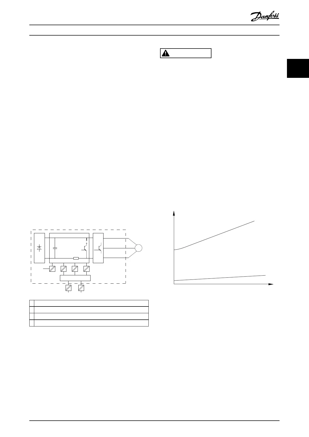
The ground leakage current is made up of several contri-
butions and depends on various system congurations
including RFI ltering, shielded motor cables, and
frequency converter power.
130BB955.12
a
b
Leakage current
Motor cable length
Illustration 2.28 Inuence the Cable Length and Power Size on
Leakage Current, P
a
>P
b
Product Overview Design Guide
MG07B102 Danfoss A/S © 03/2016 All rights reserved. 39
2 2

 Loading...


