Inputs
Product Reference Guide 59
An anti-disturbance filter, by default, is implemented in software on both inputs.
The value can be changed through the software parameter Debounce Filter. See
the Help On Line page of the Reading Phase step (Inputs) in DL.CODE for further
details on these parameters.
The connections are indicated in the following diagrams:
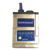
The yellow Trigger LED (Figure 15 -, 5) is on when the active state of the External
Trigger corresponds to ON.
NOTE
Polarity insensitive inputs assure full functionality even if pins A and B are
exchanged.
CBX100/500 Description
+V Power Source - External Trigger
I1A External Trigger A (polarity insensitive)
I1B External Trigger B (polarity insensitive)
-V Power Reference - External Trigger
 Loading...