68
Matrix 120
Chapter 5
Typical Layouts
The following typical layouts refer to system hardware configurations. However,
they also require the correct setup of the software configuration parameters.
Dotted lines in the figures refer to optional hardware configurations within the
particular layout.
Ethernet Connection
The Ethernet connection is possible in two different layouts.
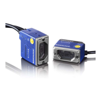
In a Point-to-Point layout the reader is connected to a local host by using a CAB-
ETH-M0x cable. There is no need to use a crossover adapter since Matrix 120
incorporates an autocross function.
Figure 50 - Ethernet Point-to-Point Layout
CAUTION
Matrix 120 readers do not have Auxiliary Serial interfaces. Therefore, neither data
monitoring nor device configuration ca be performed through this interface.
Matrix 120 devices can be configured in DL.CODE through the Ethernet, Main Serial, or
USB interfaces depending on the device model.
10-30 Vdc
Host
Matrix 120
CAB-ETH-M0x
CBX
Ethernet Interface
Auxiliary Serial Interface (Data Monitor)
External Trigger (for One Shot or Phase Mode)
CAB-1011
External Power for Matrix 120
and I/O Accessories
 Loading...