AP20 Installation and Operating Guide Version 1.25
Appendix F. H338 Optical Film Card Option F-13 Document #: 9301H39200 Ver. 1.25
F4.4.4. Azimuth and Focus
Items needed: Pink Noise test film (CAT 69P) oscilloscope, RTA, and specific tools required
to make adjustments, such as Allen/Hex Wrenches, small screw driver etc.
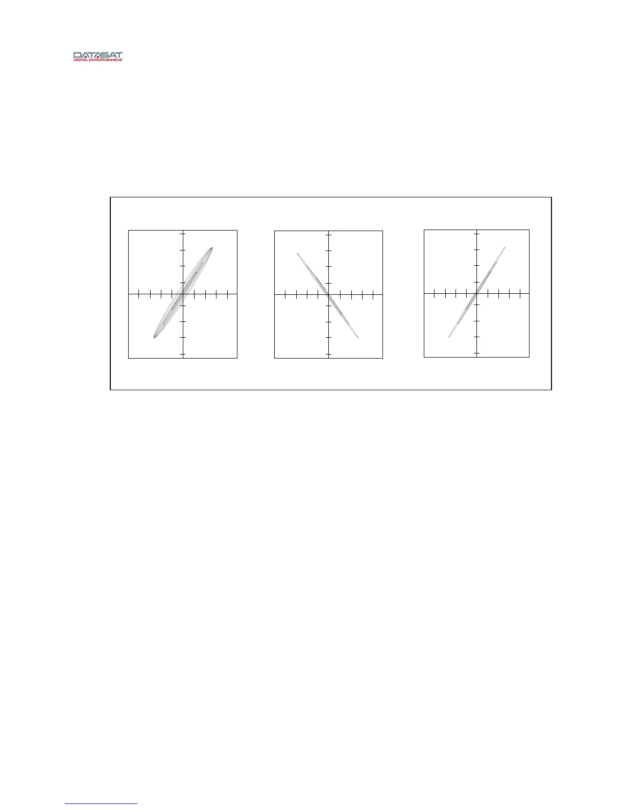
Thread Pink noise test film (CAT 69P) and start the projector. Using the oscilloscope in the
XY mode, adjust the projector’s optics (azimuth and focus controls) for the best diagonal
trace, see. Figure 16
Figure 16 – Azimuth
This can also be viewed on the AP20 screen by going to Menu (System) → Formats →
Format Options → Film Options → Film Setup and Selecting Azimuth (see Figure 15).
When Azi
muth is selected, on the right a pictorial of the azimuth adjustment is shown.
A projector select button is provided: Projector 1 = Proj1 and projector 2 = Proj2. Pressing
the button makes the selection.
The pattern on the graph shows the azimuth adjustment.
Connect the RTA to one of the test BNC connectors on the H338 preamp card. While
observing the response on the RTA, adjust the projector optics for the flattest response. This
is achieved by moving the optical lens in or out for the sharpest focus and gently rotating it for
straight azimuth. This is done while observing both the oscilloscope and RTA, see Figure 16
and Figure 17.
Once set,
move the RTA to the other test point and the results should be the same. Final slit
loss correction will be done in the next step. Depending on the design of the projector’s optics,
both focus and azimuth can interact; refer to the projector’s manufacturer for proper
adjustment procedure of azimuth and focus.
In Phase, Out of focus/azimuth Out of Phase Correct