List of Illustrations
vi 1503-0151-000 3/27/97
Section 6
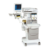
Figure 6-1 Excel 210 with mid-shelf and integrated 7900 ventilator . . . . . . . . . . .6-2
Figure 6-2 Removing the ventilator from an Excel/Modulus SE Anesthesia Gas
Machine . . . . . . . . . . . . . . . . . . . . . . . . . . . . . . . . . . . . . . . . . . . . . . . .6-3
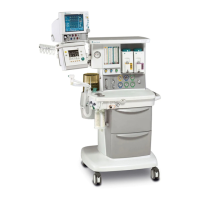
Figure 6-3 Excel 210 without mid-shelf and non-integrated 7900 ventilator . . . . .6-4
Figure 6-4 Non-integrated 7900 ventilator and mounting tray insertion . . . . . . . .6-5
Figure 6-5 Ventilator mounting tray . . . . . . . . . . . . . . . . . . . . . . . . . . . . . . . . . . .6-6
Figure 6-6 Setting up the service shelf . . . . . . . . . . . . . . . . . . . . . . . . . . . . . . . . .6-7
Figure 6-7 Put the ventilator on the service shelf . . . . . . . . . . . . . . . . . . . . . . . . .6-8
Figure 6-8 Removing the top cover screws and cover . . . . . . . . . . . . . . . . . . . . .6-9
Figure 6-9 Sub assembly locations reference . . . . . . . . . . . . . . . . . . . . . . . . . .6-10
Figure 6-10 Disconnecting cables for circuit board removal . . . . . . . . . . . . . . . . .6-11
Figure 6-11 Removing the power supply board . . . . . . . . . . . . . . . . . . . . . . . . . .6-13
Figure 6-12 Microcontroller board connector and cable identification around
manifold pressure transducer . . . . . . . . . . . . . . . . . . . . . . . . . . . . . .6-14
Figure 6-13 Microcontroller board removal . . . . . . . . . . . . . . . . . . . . . . . . . . . . . .6-15
Figure 6-14 Front panel removal . . . . . . . . . . . . . . . . . . . . . . . . . . . . . . . . . . . . .6-19
Figure 6-15 Disconnect cable. . . . . . . . . . . . . . . . . . . . . . . . . . . . . . . . . . . . . . . .6-19
Figure 6-16 Remove display board . . . . . . . . . . . . . . . . . . . . . . . . . . . . . . . . . . . .6-20
Figure 6-17 Replacing the encoder . . . . . . . . . . . . . . . . . . . . . . . . . . . . . . . . . . .6-21
Figure 6-18 Battery removal . . . . . . . . . . . . . . . . . . . . . . . . . . . . . . . . . . . . . . . . .6-22
Figure 6-19 Power Module removal . . . . . . . . . . . . . . . . . . . . . . . . . . . . . . . . . . .6-24
Figure 6-20 Power cord removal . . . . . . . . . . . . . . . . . . . . . . . . . . . . . . . . . . . . .6-25
Figure 6-21 Isolation transformer removal . . . . . . . . . . . . . . . . . . . . . . . . . . . . . .6-26
Figure 6-22 Alarm speaker removal . . . . . . . . . . . . . . . . . . . . . . . . . . . . . . . . . . .6-27
Figure 6-23 Power cord inlet connector removal . . . . . . . . . . . . . . . . . . . . . . . . .6-28
Figure 6-24 Regulator removal . . . . . . . . . . . . . . . . . . . . . . . . . . . . . . . . . . . . . . .6-29
Figure 6-25 Disconnect the flow control valve cable . . . . . . . . . . . . . . . . . . . . . .6-30
Figure 6-26 Flow control valve removal . . . . . . . . . . . . . . . . . . . . . . . . . . . . . . . .6-31
Figure 6-27 Inlet valve and solenoid switch removal . . . . . . . . . . . . . . . . . . . . . .6-32
Figure 6-28 Gas inlet valve exploded view . . . . . . . . . . . . . . . . . . . . . . . . . . . . . .6-33
Figure 6-29 Detail shuttle and U-cup seals . . . . . . . . . . . . . . . . . . . . . . . . . . . . . .6-34
Figure 6-30 Mechanical Over-pressure Bleed Off valve (MOBO) removal . . . . . .6-35
Figure 6-31 MOBO alignment and installation . . . . . . . . . . . . . . . . . . . . . . . . . . .6-37
Figure 6-32 Main manifold bottom view, exhalation manifold removed . . . . . . . .6-38
Figure 6-33 Drive gas check valve removal . . . . . . . . . . . . . . . . . . . . . . . . . . . . .6-39
Figure 6-34 Pressure sensing switch removal . . . . . . . . . . . . . . . . . . . . . . . . . . .6-40
Figure 6-35 SIB cable and pneumatic hose identification . . . . . . . . . . . . . . . . . . .6-41
Figure 6-36 Patient Interface panel cable and pneumatic hose identification.
Replace as an assembly. Shown as an exploded view for tube/
cable routing clarification. . . . . . . . . . . . . . . . . . . . . . . . . . . . . . . . . .6-42