List of Illustrations
1503-0151-000 3/27/97 v
List of Illustrations
Section 2
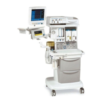
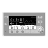
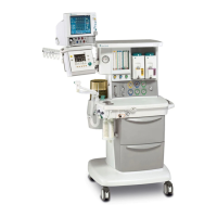
Figure 2-1 7900 Ventilator - Excel SE and Modulus SE Anesthesia System
Interface. . . . . . . . . . . . . . . . . . . . . . . . . . . . . . . . . . . . . . . . . . . . . . . .2-1
Figure 2-2 7900 Ventilator Operational Block Diagram . . . . . . . . . . . . . . . . . . . .2-2
Figure 2-3 Supply gas inlet, filtered . . . . . . . . . . . . . . . . . . . . . . . . . . . . . . . . . . .2-3
Figure 2-4 Gas Inlet Valve . . . . . . . . . . . . . . . . . . . . . . . . . . . . . . . . . . . . . . . . . .2-3
Figure 2-5 Non-Relieving Pressure Regulator . . . . . . . . . . . . . . . . . . . . . . . . . . .2-4
Figure 2-6 Flow Control Valve . . . . . . . . . . . . . . . . . . . . . . . . . . . . . . . . . . . . . . .2-4
Figure 2-7 Exhalation Manifold . . . . . . . . . . . . . . . . . . . . . . . . . . . . . . . . . . . . . . .2-5
Figure 2-8 Drive Gas Check Valve . . . . . . . . . . . . . . . . . . . . . . . . . . . . . . . . . . . .2-6
Figure 2-9 MOBO (Mechanical Over pressure Bleed Off) . . . . . . . . . . . . . . . . . .2-7
Figure 2-10 Bleed Resistor, Pressure Switch and Free Breathing Valve . . . . . . . .2-8
Figure 2-11 Electronic functional block diagram . . . . . . . . . . . . . . . . . . . . . . . . . . .2-9
Section 4
Figure 4-1 Service mode main menu . . . . . . . . . . . . . . . . . . . . . . . . . . . . . . . . . .4-3
Displays Test CPU . . . . . . . . . . . . . . . . . . . . . . . . . . . . . . . . . . . . . . . . . . . . . . 4-4
Test External RAM . . . . . . . . . . . . . . . . . . . . . . . . . . . . . . . . . . . . . . .4-5
Test Display RAM . . . . . . . . . . . . . . . . . . . . . . . . . . . . . . . . . . . . . . . .4-5
Test Flash ROM . . . . . . . . . . . . . . . . . . . . . . . . . . . . . . . . . . . . . . . . .4-6
Test EEPROM . . . . . . . . . . . . . . . . . . . . . . . . . . . . . . . . . . . . . . . . . . .4-7
Test Front Panel . . . . . . . . . . . . . . . . . . . . . . . . . . . . . . . . . . . . . . . . .4-8
Test Serial Ports . . . . . . . . . . . . . . . . . . . . . . . . . . . . . . . . . . . . . . . .4-10
Test Flow Valve . . . . . . . . . . . . . . . . . . . . . . . . . . . . . . . . . . . . . . . .4-11
Test Gas Inlet Valve . . . . . . . . . . . . . . . . . . . . . . . . . . . . . . . . . . . . .4-12
Test Pressure Limit Switch . . . . . . . . . . . . . . . . . . . . . . . . . . . . . . . .4-13
Display A/D Channels . . . . . . . . . . . . . . . . . . . . . . . . . . . . . . . . . . . 4-15
Discrete I/O Signals . . . . . . . . . . . . . . . . . . . . . . . . . . . . . . . . . . . . . .4-16
Battery Charge Status . . . . . . . . . . . . . . . . . . . . . . . . . . . . . . . . . . . .4-17
System Error Log . . . . . . . . . . . . . . . . . . . . . . . . . . . . . . . . . . . . . . .4-18
Verify Flow Output and Flow Sensors . . . . . . . . . . . . . . . . . . . . . . . .4-23
Calibrate O2 Sensor . . . . . . . . . . . . . . . . . . . . . . . . . . . . . . . . . . . . .4-24
Calibrate Flow Sensors . . . . . . . . . . . . . . . . . . . . . . . . . . . . . . . . . . .4-25
Pressure Sensitivity Calibration . . . . . . . . . . . . . . . . . . . . . . . . . . . . .4-28
Flow Valve Calibration . . . . . . . . . . . . . . . . . . . . . . . . . . . . . . . . . . . .4-30
Bleed Resistor Calibration . . . . . . . . . . . . . . . . . . . . . . . . . . . . . . . . .4-31
Sensor(s) Calibration Due . . . . . . . . . . . . . . . . . . . . . . . . . . . . . . . . .4-34
Select Altitude . . . . . . . . . . . . . . . . . . . . . . . . . . . . . . . . . . . . . . . . . .4-35
Select Drive Gas . . . . . . . . . . . . . . . . . . . . . . . . . . . . . . . . . . . . . . . .4-35
Adjust Brightness . . . . . . . . . . . . . . . . . . . . . . . . . . . . . . . . . . . . . . .4-36
Select Heliox Mode . . . . . . . . . . . . . . . . . . . . . . . . . . . . . . . . . . . . . .4-36
Section 5
Figure 5-1 Supply gas filter, Filter assembly with bowl 1503-3319-000,
Filter element 1503-3320-000 . . . . . . . . . . . . . . . . . . . . . . . . . . . . . . .5-2
Figure 5-2 Free Breathing Valve deflection tube and seat removal . . . . . . . . . . .5-3
Figure 5-3 Free Breathing Valve flapper replacement . . . . . . . . . . . . . . . . . . . . .5-4