EasyManua.ls Logo

DayTronic System 10 - Page 39

DayTronic System 10
414 pages
Print Icon
To Next Page IconTo Next Page
To Previous Page IconTo Previous Page
Loading...
A - 5
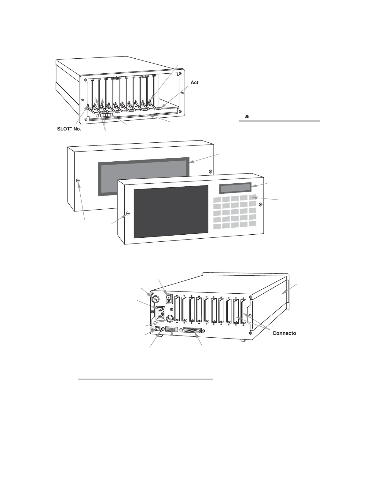
PHYSICAL LAYOUT
Actuating Lever
"A SLOT" No. 10
System Status
Indicators
Front-Panel
Two-Line LCD Display
(
Model 10K4T-KD only)
Front-Panel
Keypad
(
Model 10K4T-KD only)
Screws for Removal
of Front Panel




"A SLOT" No. 1
LCD / VFD Connector
(
for 10K4T versions with display)
Optional "A Cards"
Front-Panel
Large-Scale
LCD / VFD Display
(Model 10K4T-D /
10K4T-DA only)
Power ON/OFF
Switch
Fuse
AC Power
Connector
Voltage
Selector Switch
Plug-In Keyboard
Connector
Interface
Protocol
Switches
Computer Interface
Connector
EEPROM Write
Protect Switch

"A Card" I/O
Connectors
(for connection of
transducers and
control I/O)
Panel-Mount
Slide
Fig. 2.3.a “10K4T”
Mainframe Front Elements
Fig. 2.3.b “10K4T” Mainframe Rear Elements
“O
NTHE
A
IR
” (A-S
IZED
)

Table of Contents