B - 4
PHYSICAL LAYOUT
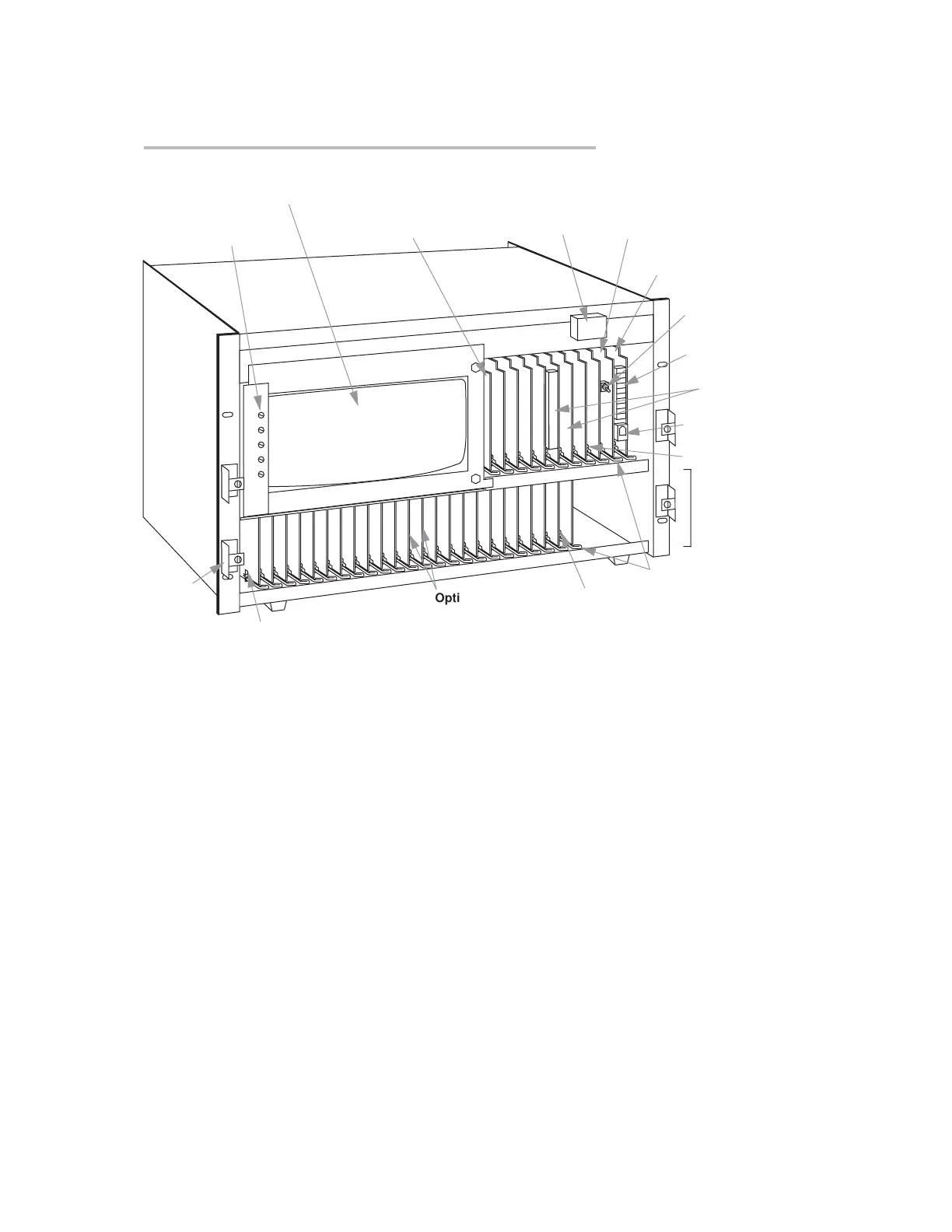
Fig. 2.1.a Mainframe Front Elements,
Models 10KN3, 10KN6, and 10KN7 (front bezel(s) removed)
EEPROM Write
Protect Switch
System Status
Indicators
RS-232 Interface Card
(Interface Protocol Switches are also
mounted on this board)
Central Processor Card
Plug-In Keyboard
Connector
Power ON/OFF
Button
Video Text Card
(occupies B Slot No. 1)**
Optional
"B Cards"
"B SLOT" No. 9
"A CARD DECK"
No. 1***
Swell
Latch
Bracket
Internal Monochrome Monitor*
Internal CRT Controls*
Optional
"A Cards"
"A SLOT" No. 24
Actuating Lever
"A SLOT" No. 1
* Model 10KN7 mainframes only. On mainframes with the “E” (Extended B Rack) Option,
the CRT space will be occupied by additional B Slots.
** The Video Signal Card and any other optional video cards are located to the left of the
Video Text Card (connected to the mainframe’s Video Backplane). For mainframes
with the “E” (Extended B Rack) Option, the Video Text Card will occupy B Slot No. 4.
*** Not present on the Model 10KN3 mainframe. A “10KN6” or “10KN7” mainframe may
have up to four A Decks in all.
“O
NTHE
A
IR
” (B-S
IZED
)
 Loading...