B - 5
PHYSICAL LAYOUT
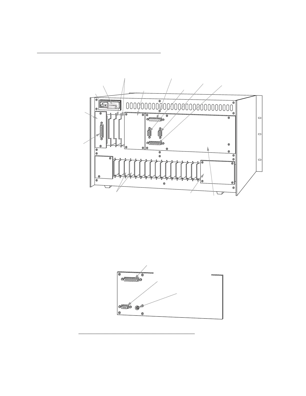
* Many “B Cards” come with their own rear connector assemblies (not shown here).
** Not present on the 10KN3 mainframe, which has no “A Cards.”
Computer Interface
Connector Panel
(NOT TO BE REMOVED)
RS-232
Computer
Interface
Connector
AC Power Connector
Fuse and
Power Selector Board
"B Card" I/O Connectors*
(for connection of digital/logic devices,
satellite units, computers, etc.)
Removable "B
Slot" Cover
RS-232 Formatted
Output Connector
(requires optional Model
10VFO132 Formatted
Output Card for operation)
RS-232
Touchscreen
Connector
Removable "A Slot" Cover**
"A Card" I/O Connectors**
(for connection of transducers and
control I/O)
VGA
Input
VGA
Output
10KN6
Video Connector Panel
(NOT TO BE REMOVED)
Fig. 2.1.b Mainframe Rear Elements,
Models 10KN3, 10KN6, and 10KN7 (NOTE: 10KN7 Video
Connector Panel is shown separately in Fig. 2.1.c)
"RGB" Output
(to external CGA color monitor)
RS-170 Output
(to external
monochrome monitor)
RS-232 Formatted Output Connector
(requires optional Model 10VFO132 Formatted
Output Card for operation)
Fig. 2.1.c Model 10KN7 Video Connector Panel
“O
NTHE
A
IR
” (B-S
IZED
)
 Loading...