B - 6
PHYSICAL LAYOUT
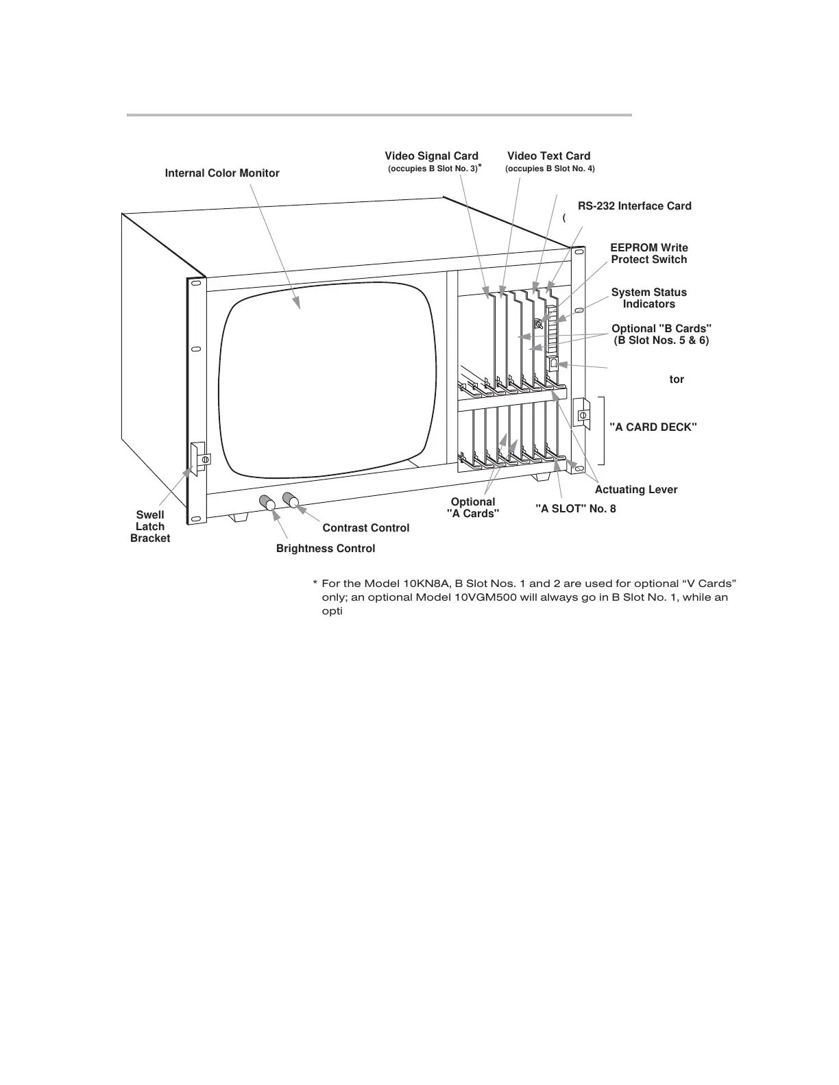
Fig. 2.2.a Mainframe Front Elements, Model 10KN8A (front bezel removed)
Optional
"A Cards"
"A SLOT" No. 8
Actuating Lever
"A CARD DECK"
Swell
Latch
Bracket
Internal Color Monitor
EEPROM Write
Protect Switch
System Status
Indicators
RS-232 Interface Card
(Interface Protocol Switches are also
mounted on this board)
Central Processor Card
Plug-In Keyboard
Connector
Optional "B Cards"
(B Slot Nos. 5 & 6)
Brightness Control
Contrast Control
Video Signal Card
(occupies B Slot No. 3)*
Video Text Card
(occupies B Slot No. 4) *
*For the Model 10KN8A, B Slot Nos. 1 and 2 are used for optional “V Cards”
only; an optional Model 10VGM500 will always go in B Slot No. 1, while an
optional Model 10VFO132 will go in B Slot No. 2.
“O
NTHE
A
IR
” (B-S
IZED
)
 Loading...