B - 7
PHYSICAL LAYOUT
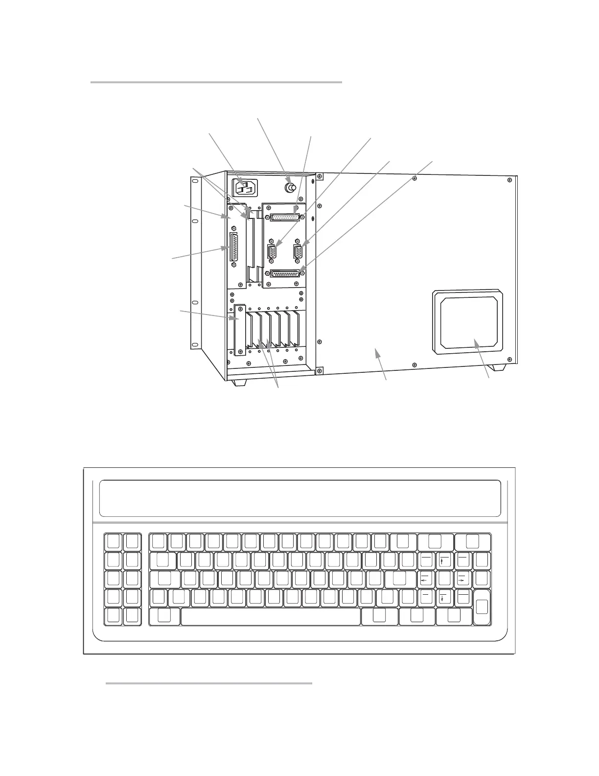
Fig. 2.2.b Mainframe Rear Elements, Model 10KN8A
Computer Interface
Connector Panel
(
NOT TO BE REMOVED)
RS-232
Computer
Interface
Connector
AC Power Connector
"B Card" I/O
Connectors*
(for connection of digital/logic
devices, satellite units,
computers, etc.)
RS-232 Formatted
Output Connector
(requires optional Model
10VFO132 Formatted
Output Card for operation)
RS-232 Touchscreen
Connector
(NOT NORMALLY USED
WITH THE MODEL 10KN8A)
Removable
"A Slot" Cover
"A Card" I/O Connectors
(for connection of transducers and
control I/O)
VGA
Input
VGA
Output
Video Connector Panel
(
NOT TO BE REMOVED)
Combined Power ON-OFF
and Circuit Breaker Button
Replaceable
Fan Filter
* Many “B Cards” come
with their own rear con-
nector assemblies (not
shown here).
F3
F1
F5
Yes
F7
Page
F10
Step
F8
Cal
F9
Chan
F2
F4
F6
No
Esc
2 3 4 5 6 7 8 9 0
_
-
+
=
Q W E R T Y U I O P
{
[
}
]
’
~
Grn
Back
Grnd
Yel
Clear
Tab
A S D F G H J K L
:
;
"
Shift
|
\
Z
X C V B N M
< > ?
/
Ctrl
Back
Space
Systm
Confg
Caps
Lock
Retrn
Shift
Video
Formt
Blk
Red
Wht
Exit
Line
Feed
Blu LtBlu
Insrt Dlete
Home
1
'
.
,
Vlt
Hght
Begin
Data
End
Data
Width
!
@
#
$
%
^
&
*
(
)
<LOGO>
_
Fig. 2.3 Model 10P80A Extended Keyboard
“O
NTHE
A
IR
” (B-S
IZED
)
 Loading...