24 Part No. 057-009 5110 Operating Manual Issue 3.3 3/1/2006
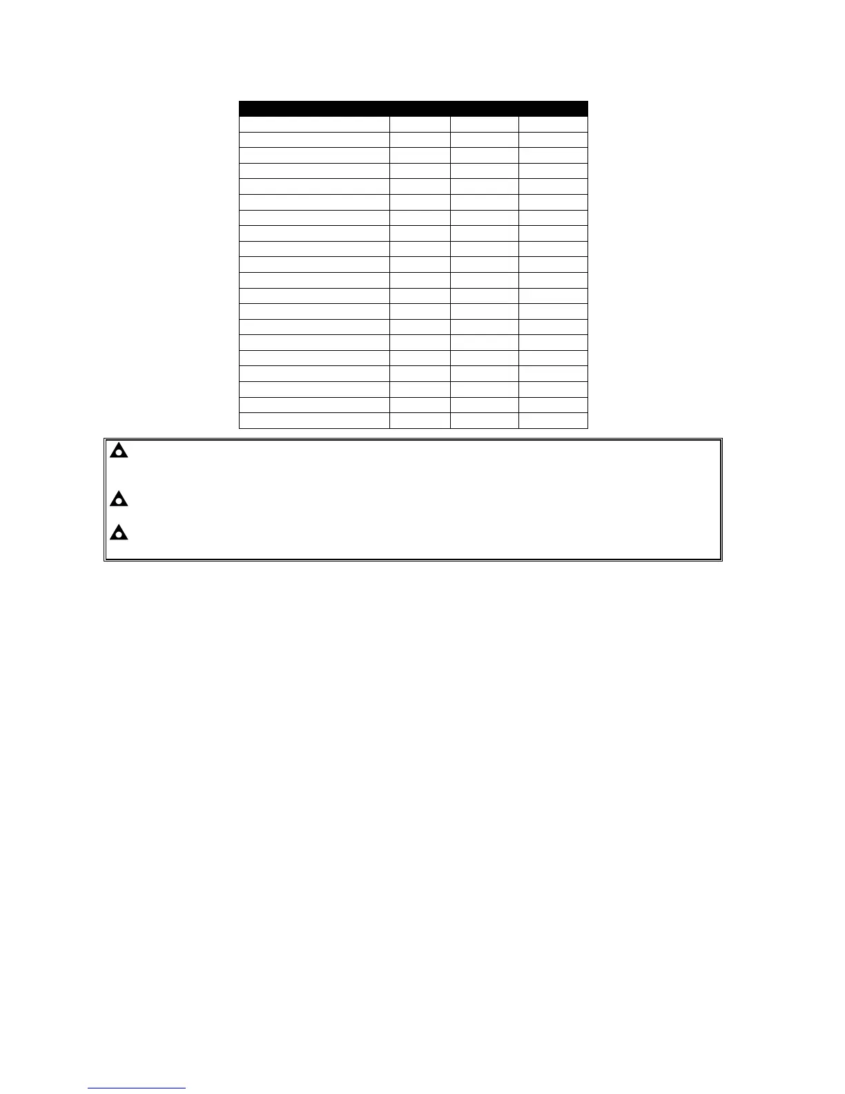
9.4 TIMERS & ANALOGUE SETTINGS
Parameter Type Default Max
0 - Start delay Timer
5s
60s
1 - Preheat Timer
0s
60s
2 - Crank attempt Timer
10s
60s
3 - Crank rest Timer
10s
60s
4 - Safety delay Timer
8s
60s
5 - Warming up Timer
0s
60m
6 - Return delay Timer
30s
60m
7 - Cooling run Timer
60s
60m
8 - E.T.S. solenoid hold Timer
0s
60s
9 - Sensor fail delay Timer
2s
5s
10 - Fail to Stop Delay Timer
60s
60s
11 - Low Oil Pressure Trip
15PSI
150PSI
12 - High Temperature Trip
95°C
150°C
13 - Under Speed Trip
1250RPM
3600RPM
14 - Over Speed Trip
1750RPM
5000RPM
15 - Underfrequency Trip
40Hz
60Hz
16 - Overfrequency Trip
57Hz
72Hz
17 - Charge Alt Failure Warning
8V DC
25V DC
18 - Flywheel teeth Value
0
300
19 - CT Primary Value
500A
6000A
NOTE:- Setting a timer to zero (0) will disable it. Timer settings increment from 0 to 60s in
steps of 1s and from 1 minute to the maximum value in steps of 30 seconds (0.5 minutes) (where
applicable)
NOTE:- Setting Flywheel teeth to zero (0) will disable magnetic pickup speed sensing. In this
instance, engine speed is derived from the alternator output frequency.
NOTE:- CT values increment from 10-100 in steps of 10A, and from 100 to 6000A in steps of
50A. CT secondary must be 5A.