48 Part No. 057-009 5110 Operating Manual Issue 3.3 3/1/2006
18.7 FRONT PANEL CONFIGURATION (ORIGINAL 5110)
In April 2005, the 5110 controller was updated to include PC configuration. At this time, a few minor
changes to the front panel configuration were also made.
This section details the configuration editor of the “Original” 5110 module. To identify the “original” and
“new” controllers, See the section entitled
Identification of “original” 5110 and “new” 5110 from V2
onwards
elsewhere in this manual.
NOTE:- PC Configuration is not possible on the “original” 5110 controller. All options must
be edited using the Front Panel Configuration Editor.
TIMERS & ANALOGUE SETTINGS
Parameter Type
Default
Max
0 - Start delay Timer 5s 60s
1 - Preheat Timer 0s 60s
2 - Crank attempt Timer 10s 60s
3 - Crank rest Timer 10s 60s
4 - Safety delay Timer 8s 60s
5 - Warming up Timer 0s 60s
6 - Return delay Timer 30s 60m
7 - Cooling run Timer 60s 60m
8 - E.T.S. solenoid hold Timer 0s 60s
9 - Low Oil Pressure Trip 15PSI 150PSI
10 - High Temperature Trip 95°C 150°C
11 - Under Speed Trip 1250RPM 3600RPM
12 - Over Speed Trip 1750RPM 5000RPM
13 – Underfrequency Trip 40Hz 60Hz
14 - Overfrequency Trip 57Hz 72Hz
15 - Charge Alt Failure Warning 8V DC 25V DC
16 - Flywheel teeth Value 0 300
17 - CT Primary Value 500A 6000A
NOTE:- Setting a timer to zero (0) will disable it. Timer settings
increment from 0 to 60s in steps of 1s and from 1 minute to the
maximum value in steps of 30 seconds (0.5 minutes) (where
applicable)
NOTE:- Setting Flywheel teeth to zero (0) will disable magnetic
pickup speed sensing. In this instance, engine speed is derived from
the alternator output frequency.
NOTE:- CT values increment from 10-100 in steps of 10A, and
from 100 to 6000A in steps of 50A. CT secondary must be 5A.
LIST ITEM SETTINGS
Factory default settings are in bold italicised text.
Parameter Selections
18 - Alternator poles 0,2,4,6,8
19 - Oil Pressure 0 - Switch close to activate
transducer 1 - Switch open to activate
2 - VDO 0-5bar
3 - VDO 0-10bar
4 - Datcon 0-5bar
5 - Datcon 0-10bar
20 - Coolant temp 0 - Switch close to activate
transducer 1 - Switch open to activate
2 - VDO 0-120
°
C
3 - Datcon High
21 - Fast loading 0 - No
enabled 1 - Yes
22 - AC system 1 - 1 phase 2 wire
3 - 3 phases 4 wires
23 - Oil pressure 0 - Bar/PSI
display units 1 - kPa
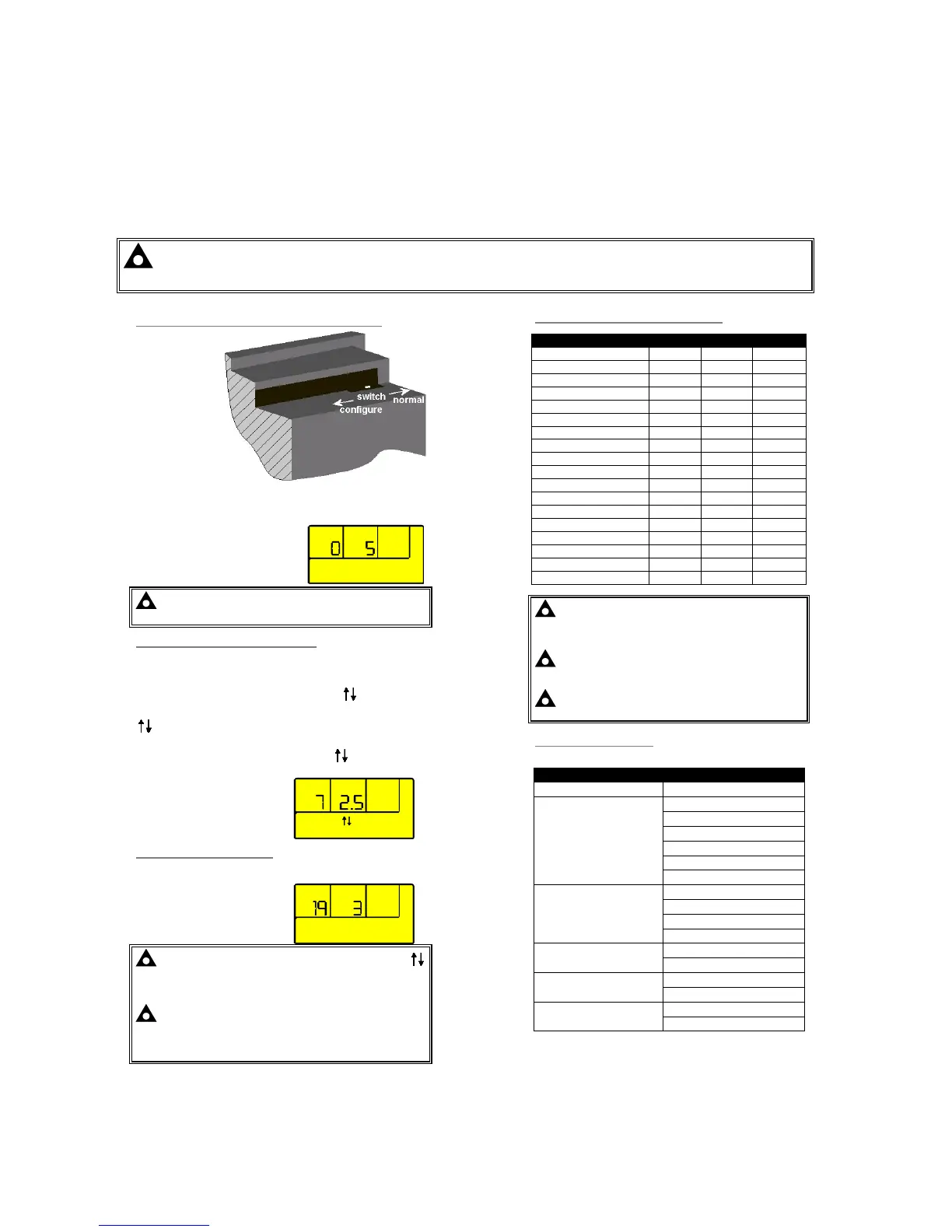
ACCESSING THE CONFIGURATION EDITOR
Operate the
Configuration
mode switch into
the “configure”
position. (This
recessed switch is
located on the
rear of the module
in the top right
corner when
viewing the
module from the
back.)
The LED indicator beside the AUTO 9 button will flash to show
that the module is now in configuration mode. While in
configuration mode, all normal operation is suspended.
The first configurable parameter is
displayed. In this example, the
Start delay timer (parameter 0). Is
currently set to 5s.
NOTE:- The module must be in STOP mode with the
engine at rest in order to enter the configuration editor.
EDITING AN ANALOGUE VALUE
Enter the configuration editor as described above.
Press the + / – buttons to select the parameter you wish to
change using the following lists as a reference.
Press the 9 button to enter adjust mode.The
icons in the
module display will flash. Pressing the + or – buttons while the
icons are flashing will change the selected parameter to the
desired value.
Press the 9 button to ‘save’ the value. The
icons will stop
flashing to confirm that it has been saved.
The parameter being displayed in
this example is the cooling timer
(parameter 7). It’s current value is
2.5mins (2mins 30secs).
EDITING A ‘LIST’ VALUE
Some configuration parameters have a list of options to select
from. These include input and output settings.
This example shows the setting
for oil pressure transducer
(parameter 19). It’s current setting
is 3 (‘VDO 0-10bar’ from the list
shown opposite).
NOTE:- When in adjust mode (indicated by the flashing
icons in the module display), pressing the O (stop mode) button
will cancel any changes made to the current parameter,
reverting to the last ‘saved’ value. This also exits adjust mode.
NOTE:- To exit the front panel configuration editor at any
time, move the Configuration mode switch back into the
“normal” position. Ensure you save any changes you have
made by pressing the 9 button first if necessary.