Home
Dell
Server
PowerEdge C6220
Page 25
Dell PowerEdge C6220 - Page 25
316 pages
Manual
Save Page as PDF
To Next Page
To Next Page
To Previous Page
To Previous Page
Loading...
About Y
our System |
25
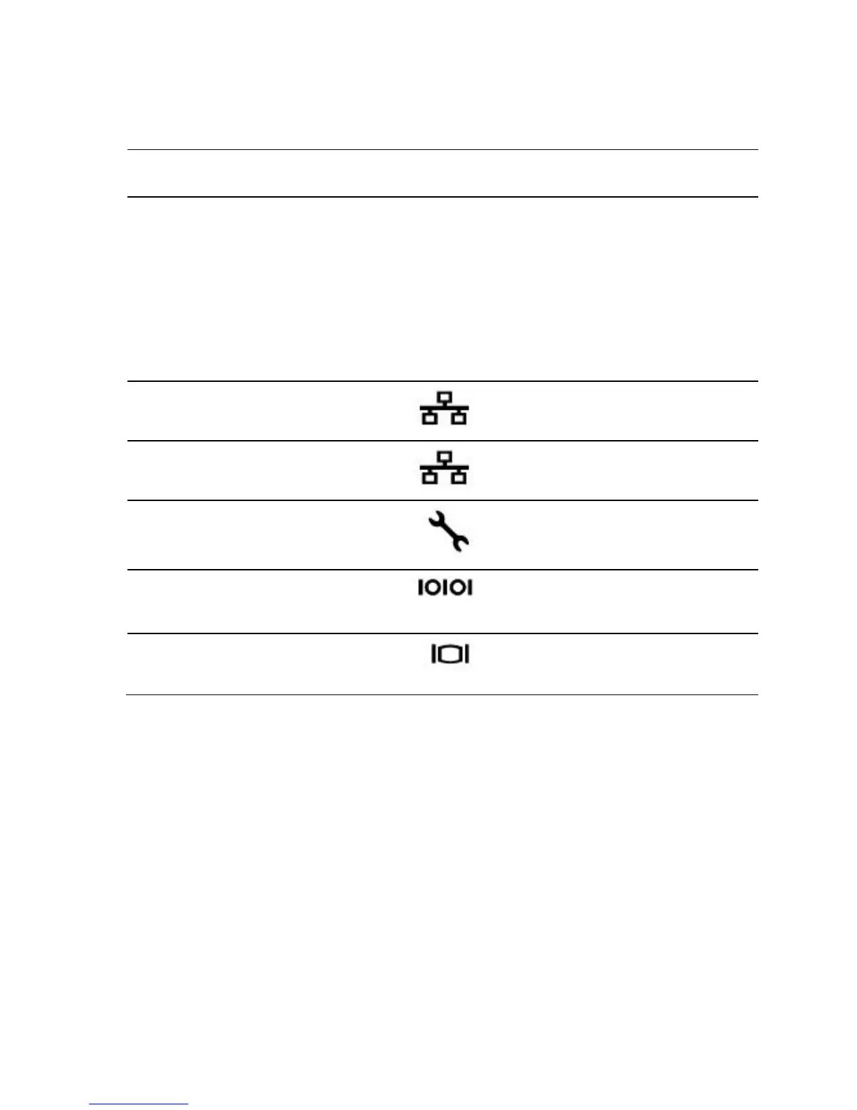
Item
Indicator
, Button
Or Connector
Icon
Description
4
System identific
ation
indicator
Both the systems management
software
and the identification
buttons locate
d on the front can
cause the indicator to flash blue
to identify a particular system
and system board. Lig
hts amber
when the system nee
ds attention
due to a problem.
5
LAN
connector 1
Embedded 10/100/1000 NIC
connectors.
6
LAN
connector 2
Embedded 10/100/1000 NIC
connectors.
7
Management port
Dedicated management port.
8
Serial port
Connects a serial device
to the
system.
9
VGA port
Connects a VGA display to the
system.
24
26
Table of Contents
Main Page
Default Chapter
3
Table of Contents
3
About Your System
12
Accessing System Features During Startup
12
Front-Panel Features and Indicators
13
Hard-Drive Indicator Patterns
18
Service Tag
21
Back Panel Features and Indicators
24
System-Board Assembly Configurations
27
LAN Indicator Codes
29
Power and System Board Indicator Codes
31
Power Supply Indicator Codes
32
1400W
32
1200W
33
BMC Heart Beat LED
34
Post Error Code
35
Collecting System Event Log (SEL) for Investigation
35
System Event Log
39
Processor Error
39
Memory ECC
40
PCI-E Error
41
IOH Core Error
42
SB Error
43
POST Start Event
44
POST End Event
44
POST Error Code Event
45
BIOS Recovery Event
46
ME Fail Event
47
SEL Generator ID
47
Sensor Data Record
48
Other Information You May Need
53
Fresh Air Support
53
Micro SD Card and SD Card Socket Location
57
Using the System Setup Program
58
Start Menu
58
System Setup Options at Boot
58
Boot Manager
59
Console Redirection
61
Enabling and Configuring Console Redirection
62
Main Menu
66
Main Screen
66
Advanced Menu
68
Power Management
69
Chassis Power Management
70
CPU Configuration
71
Prefetch Configuration
75
Memory Configuration
76
SATA Configuration
78
PCI Configuration
81
Embedded Network Devices
83
ISCSI Remote Boot
85
Active State Power Management Configuration
86
PCI Slot Configuration
87
USB Configuration
88
Security Menu
89
Server Menu
91
Set BMC LAN Configuration
93
Remote Access Configuration
94
Boot Menu
96
Exit Menu
97
Command Line Interfaces for Setup Options
98
Installing System Components
130
Safety Instructions
130
Recommended Tools
130
Inside the System
131
Hard Drives
133
Removing a 3.5-Inch Hard-Drive Blank
133
Installing a 3.5-Inch Hard-Drive Blank
133
Removing a 2.5-Inch Hard-Drive Blank
134
Installing a 2.5-Inch Hard-Drive Blank
134
Removing a Hard-Drive Carrier
135
Installing a Hard-Drive Carrier
136
Removing a Hard Drive from a Hard-Drive Carrier
136
Installing a Hard Drive into a Hard-Drive Carrier
138
Power Supplies
138
Removing a Power Supply
139
Installing a Power Supply
140
System-Board Assembly
141
Removing a System-Board Blank Tray
141
Installing a System-Board Blank Tray
142
Removing a System-Board Assembly
142
Installing a System-Board Assembly
143
Air Baffle
144
Removing the Air Baffle
144
Installing the Air Baffle
145
Heat Sinks
145
Removing the Heat Sink
145
Installing the Heat Sink
146
Processors
147
Removing a Processor
147
Installing a Processor
149
Interposer Extender for 2U Node
151
Removing the Interposer Extender for 2U Node
151
Installing the Interposer Extender for 2U Node
152
Removing the Interposer Extender Tray for 2U Node
153
Installing the Interposer Extender Tray for 2U Node Tray
154
Expansion-Card Assembly and Expansion Card
154
Removing the Expansion Card for 1U Node
154
Installing the Expansion Card for 1U Node
157
Removing the Expansion Card for 2U Node
158
Installing the Expansion Card for 2U Node
162
Raid Card
164
Summary of LSI 9265-8I with RAID Battery, LSI 9210-8I HBA and LSI 9285-8E with RAID Battery
164
LSI 9265-8I Card
165
Removing the LSI 9265-8I Card for 1U Node
165
Installing the LSI 9265-8I Card for 1U Node
168
Cable Routing for LSI 9265-8I Card (1U Node)
169
Removing the LSI 9265-8I Card for 2U Node
171
Installing the LSI 9265-8I Card for 2U Node
175
Cable Routing for LSI 9265-8I Card (2U Node)
176
LSI 9265-8I RAID Battery
180
Removing the LSI 9265-8I Raid Battery Assembly
180
Installing the LSI 9265-8I Raid Battery Assembly
181
Removing the LSI 9265-8I RAID Battery
182
Installing the LSI 9265-8I RAID Battery
183
Riser Card
184
Optional Riser Cards
184
Removing the Riser Card for 1U Node
186
Installing the Riser Card for 1U Node
187
Cable Routing for Riser Card (1U Node)
187
Removing the Riser Card for 2U Node
188
Installing the Riser Card for 2U Node
191
Cable Routing for Riser Card (2U Node)
192
Optional Mezzanine Cards
193
Removing the LSI 2008 SAS Mezzanine Card
193
Installing the LSI 2008 SAS Mezzanine Card
194
Cable Routing for LSI 2008 SAS Mezzanine Card (1U Node)
195
Cable Routing for LSI 2008 SAS Mezzanine Card (2U Node)
196
Removing the 1Gbe Mezzanine Card
199
Installing the 1Gbe Mezzanine Card
201
Removing the 10Gbe Mezzanine Card
202
Installing the 10Gbe Mezzanine Card
205
Mezzanine-Card Bridge Board
206
Removing the Mezzanine-Card Bridge Board
206
Installing the Mezzanine-Card Bridge Board
207
System Memory
208
Memory Slot Features
208
Supported Memory Module Configuration
208
Removing the Memory Modules
210
Installing the Memory Modules
212
System Battery
214
Replacing the System Battery
214
System Board
216
Removing a System Board
216
Installing a System Board
217
Opening and Closing the System
218
Opening the System
218
Closing the System
219
Cooling Fans
220
Removing a Cooling Fan
220
Installing a Cooling Fan
222
Power Distribution Boards
223
Removing a Power Distribution Board
223
Installing a Power Distribution Board
228
Cable Routing for Power Distribution Board
230
Middle Planes
233
Removing the Middle Planes
233
Installing the Middle Planes
240
Cable Routing for Middle Plane to Direct Hard-Drive Backplane
242
Cable Routing for Middle Plane to 2.5" Hard-Drive Backplane for Expander Configuration
247
Direct Backplanes
249
Removing the Direct Backplane
249
Installing the Direct Backplane
254
2.5-Inch Hard Drive Expander Configuration
256
Removing the 2.5-Inch Hard Drive Backplane for Expander Configuration
256
Installing the 2.5-Inch Hard Drive Backplane for Expander Configuration
264
Front Panels
265
Removing the Front Panel
265
Installing the Front Panel
267
Sensor Boards
269
Removing the Sensor Board for 3.5" Hard-Drive System
269
Installing the Sensor Board for 3.5" Hard-Drive System
270
Cable Routing for Sensor Board and Front Panel for 3.5" Hard Drive System
271
Removing the Sensor Board for 2.5" Hard-Drive System
273
Installing the Sensor Board for 2.5" Hard-Drive System
275
Cable Routing for Sensor Board and Front Panel for 2.5" Hard Drive System
276
Troubleshooting Your System
278
Minimum Configuration to POST
278
Safety First - for You and Your System
278
Installation Problems
279
Troubleshooting System Startup Failure
279
Troubleshooting External Connections
279
Troubleshooting the Video Subsystem
280
Troubleshooting a USB Device
280
Troubleshooting a Serial I/O Device
281
Troubleshooting a NIC
281
Troubleshooting a Wet System
282
Troubleshooting a Damaged System
283
Troubleshooting the System Battery
284
Troubleshooting Power Supplies
285
Troubleshooting System Cooling Problems
285
Troubleshooting a Fan
286
Troubleshooting System Memory
287
Troubleshooting a Hard Drive
289
Troubleshooting a Storage Controller
290
Troubleshooting Expansion Cards
291
Troubleshooting Processors
292
IRQ Assignment Conflicts
293
Jumpers and Connectors
294
System Board Connectors
294
Backplane Connectors
295
3.5" Hard-Drive Direct Backplane
295
2.5" Hard-Drive Direct Backplane
298
2.5" Hard-Drive Expander Backplane
300
Middle Plane Connectors
301
Interposer Extender for 2U Node Connectors
302
LSI 2008 SAS Mezzanine Card Connectors
303
1Gbe Mezzanine Card Connectors
304
10Gbe Mezzanine Card Connectors
305
Power Distribution Board 1 Connectors
306
Power Distribution Board 2 Connectors
307
Sensor Board Connectors
307
Jumper Settings
308
System Configuration Jumper Settings
308
Direct Backplane Jumper Settings
309
Getting Help
310
Contacting Dell
310
Index
311
Other manuals for Dell PowerEdge C6220
Installation Guide
26 pages
Using Instructions
68 pages
Getting Started Guide
66 pages
Technical Guide
35 pages
Getting Started
86 pages
Related product manuals
Dell PowerEdge C6220 II
349 pages
Dell PowerEdge C6100
160 pages
Dell PowerEdge C6320
183 pages
Dell PowerEdge C6400
88 pages
Dell PowerEdge C6600
103 pages
Dell EMC PowerEdge C6420
127 pages
Dell EMC PowerEdge C6525
80 pages
Dell EMC PowerEdge C6520
89 pages
Dell PowerEdge C1100
144 pages
Dell PowerEdge
56 pages
Dell PowerEdge T30
107 pages
Dell PowerEdge 860
140 pages