Steps
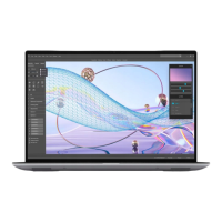
1. Remove the two (T5, M1.4x4) Torx screws that secure the display FPC holder to the system board.
2. Remove the two (T5, M1.4x4) Torx screws that secure the display FPC to the system board.
3. Disconnect the display FPC from the system board and remove the interposer board.
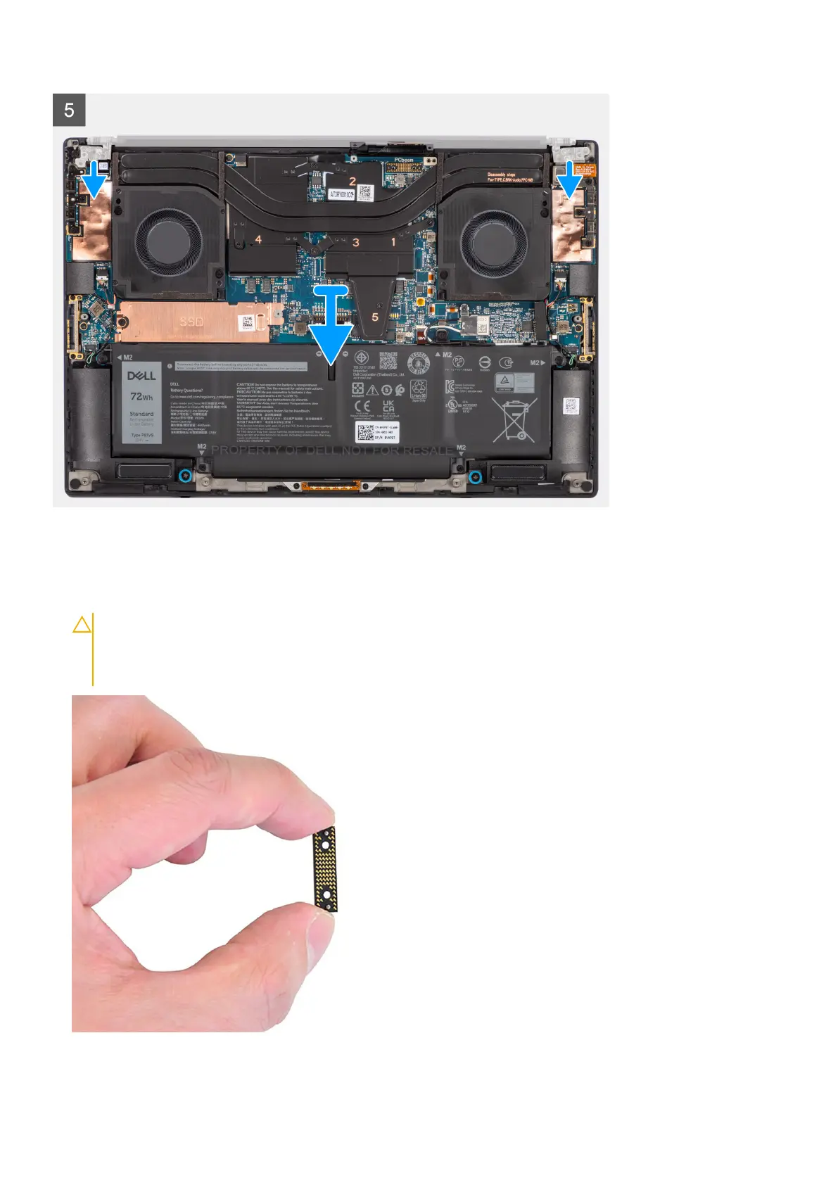
CAUTION:
Technicians must remove the interposer board immediately after disconnecting the display FPC
to prevent the board from falling out of the system during subsequent removal procedures. The pins on the
interposer board are fragile. Avoid contact with the pins on the board. Instead, handle the board by lifting
and holding from the edges or the sides.
4. Remove the six (M2.5x5) screws that secure the display assembly to the palm-rest and keyboard assembly.
42
Removing and installing components