Figure 62. Removing the system board
Steps
1. Remove the four Torx screws (T5, M1.4x4) that secure the display FPC holder and display FPC to the system board.
2. Disconnect the display FPC from the system board and remove the interposer board.
CAUTION:
Technicians must remove the interposer board immediately after disconnecting the display FPC to
prevent the board from falling out of the computer during subsequent removal procedures. The pins on the
interposer board are fragile. Avoid contact with the pins on the board. Instead, handle the board by lifting
and holding from the edges or the sides.
3. Loosen the single captive screw (M1.6x2.3) that secure the WLAN bracket to the system board.
4. Disconnect the antenna cables from the WLAN module and unroute them from the metal clips on the system board.
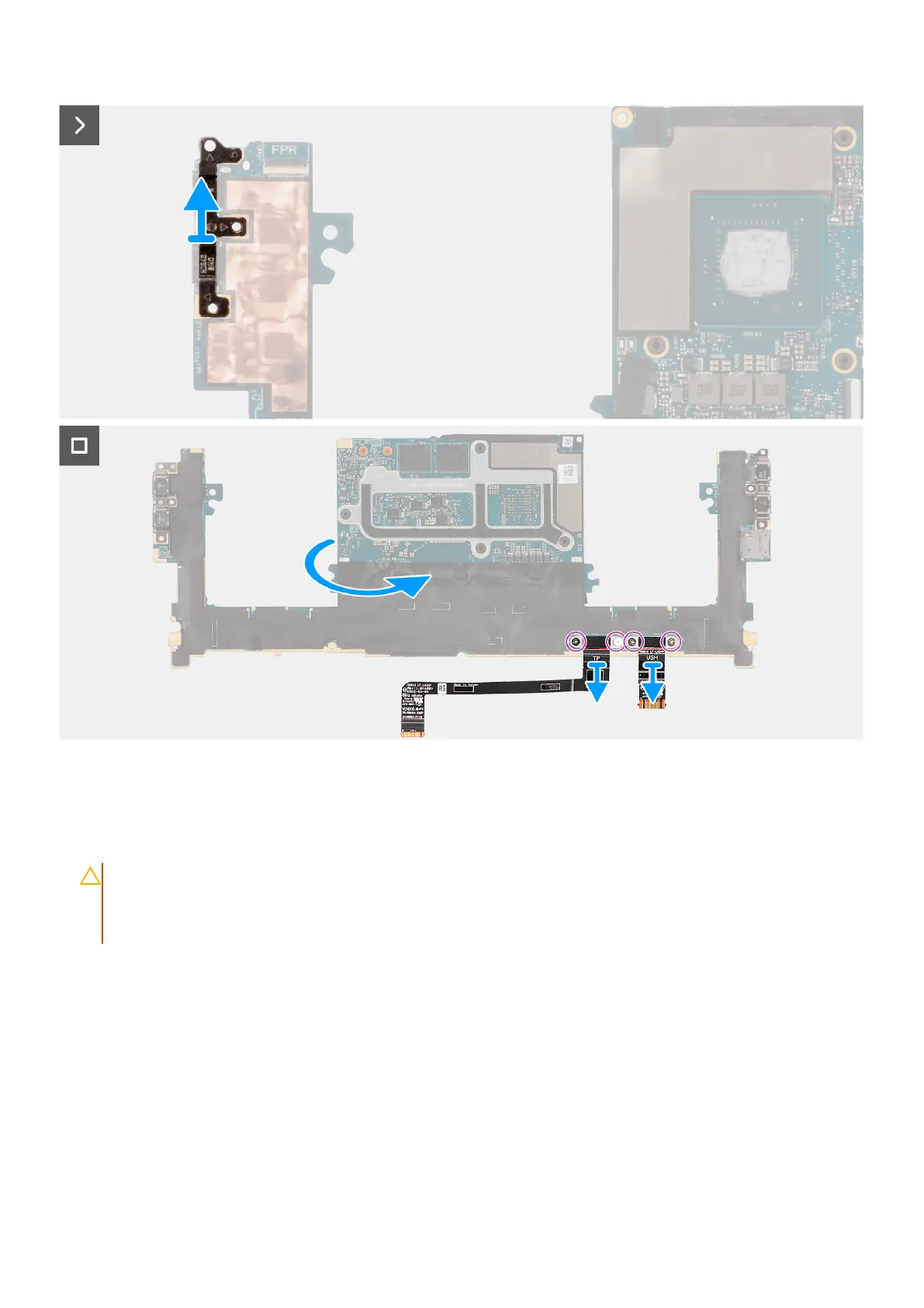
5. Open the latch and disconnect the power button board with fingerprint reader FPC from the system board.
6. Open the latch and disconnect the USH board FPC (for models that are shipped with a USH board) and touchpad FPC from
their respective connectors.
7. Open the latch and disconnect the battery LED FPC from the system board.
8. Peel the left and right tweeter speakers from their compartments on the palm-rest and keyboard assembly.
9. Unroute the tweeter speaker cables from the metal clips on the system board.
10. Disconnect the left and right speaker cables from the system board.
11. Remove the three screws (M2x4) that secure the right USB Type-C bracket to the system board.
12. Remove the three screws (M2x4) that secure the system board to the palm-rest and keyboard assembly.
Removing and installing Field Replaceable Units (FRUs)
83