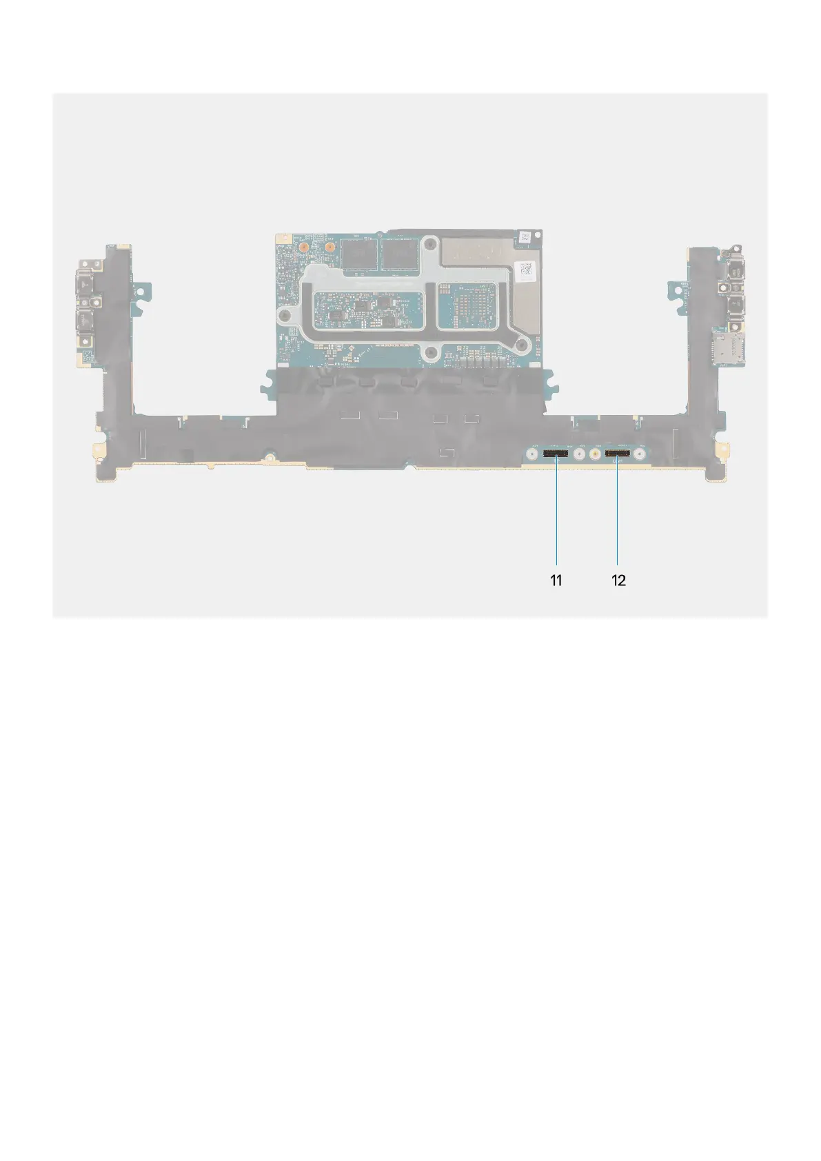
Figure 65. Connectors on your system board
1. Power button with fingerprint reader FPC connector
2. Audio jack FPC connector
3. Processor-fan cable connector
4. Left tweeter speaker cable connector
5. Integrated WLAN card
6. Battery LED FPC connector
7. Battery cable connector
8. M.2 2230/2280 solid state drive slot
9. Graphics-card fan cable connector
10. Right tweeter speaker cable connector
11. Touchpad FPC connector
12. USH board FPC connector
The figure indicates the location of the system board and provides a visual representation of the installation procedure.
86
Removing and installing Field Replaceable Units (FRUs)