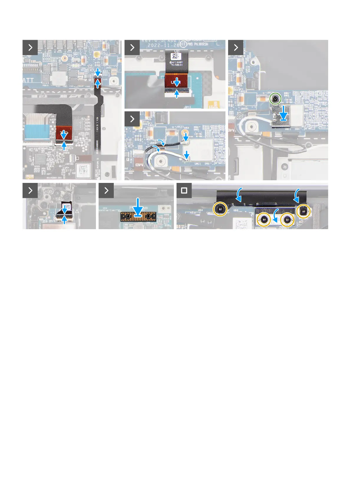
Figure 68. Installing the system board
Steps
1. Align the screw holes on the USH board FPC (for models that are shipped with a USH board) and touchpad FPC.
2. Replace the four screws (M1.4x1.2) to secure the USH board FPC (for models that are shipped with a USH board) and
touchpad FPC to the system board.
3. Flip-over the system board and align the screw holes on the system board with the holes on the palm-rest and keyboard
assembly.
4. Replace the USB Type-C bracket at the upper-right side of the system board.
5. Replace the three screws (M2x4) to secure the system board to the palm-rest and keyboard assembly.
6. Replace the three screws (M2x4) to secure the right USB Type-C bracket on the system board.
7. Adhere the left and right tweeter speakers to their compartments on the palm-rest and keyboard assembly and route the
speaker cables through the metal clips on the system board.
8. Connect the left and right speaker cables to the connectors on the system board.
9. Connect the battery LED FPC to the system board and close the latch.
10. Connect the USH board FPC (for models that are shipped with a USH board) and touchpad FPC to their respective
connectors and close the latch.
11. Connect the power button board with fingerprint reader FPC to the connector on the system board and close the latch.
12. Route the WLAN antenna cables using the metal clips on the system board and connect them to the WLAN module.
13. Tighten the single captive screw (M1.6x2.3) to secure the WLAN bracket on the system board.
14. Place the interposer board and connect the display FPC to the system board.
15. Replace the four Torx screws (T5, M1.4x4) to secure the display FPC holder and display FPC to the system board.
Next steps
1. Install the heat sink for integrated graphics or heat sink for discrete graphics.
2. Install the audio jack.
3. Install the graphics-card fan.
4. Install the processor fan.
Removing and installing Field Replaceable Units (FRUs)
89