3. Remove the M.2 2230 solid state drive or M.2 2280 solid state drive.
4. Remove the battery.
5. Remove the processor fan.
6. Remove the graphics-card fan.
7. Remove the audio jack.
8. Remove the system board.
NOTE: The system board can be removed or installed together with the heat-sink attached. This simplifies the
procedure and avoids breaking the thermal bond between the system board and the heat-sink.
About this task
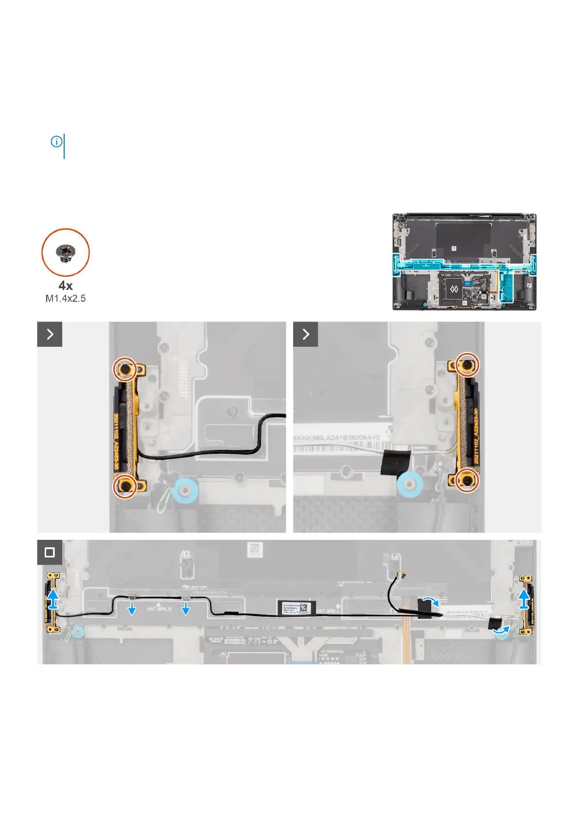
The figure indicates the location of the WLAN antennas and provides a visual representation of the removal procedure.
Figure 73. Removing the WLAN antennas
Steps
1. Remove the two captive screws (M1.4x2.5) that secure the auxiliary antenna on the palm-rest and keyboard assembly.
2. Remove the two captive screws (M1.4x2.5) that secure the main antenna on the palm-rest and keyboard assembly.
94
Removing and installing Field Replaceable Units (FRUs)