Chapter 3 Connections and Wiring|ASDA-B Series
3-12 Revision January 2009
3.3 Input / Output Interface Connector -CN1
The CN1 Interface Connector provides access to three signal groups:
i General interface for the analog speed and torque control, encoder reference signal from the motor,
open collector and line driver inputs, and reference voltages.
ii 6 programmable Digital Inputs (DI), can be set via parameters P2-10 ~ P2-15
iii 3 programmable Digital Outputs (DO), can be set via parameters P2-18 ~ P2-20
A detailed explanation of each group is available in Section 3.3.2, Tables 3.A, 3.B & 3.C.
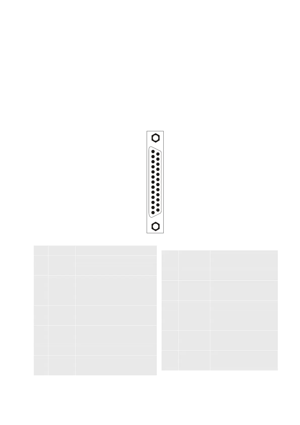
3.3.1 CN1 Terminal Identification
Figure 3.7 The Layout of CN1 Drive Connector:
1
14
13
25
CN1 Terminal Signal Identification
1 D03+
Digital output
14 DI6- Digital input
2 DO2+
Digital output
15 DI5- Digital input
3 DI4- Digital input
16 DO1+
Digital output
4 COM+ DI input common voltage rail
17 DI1- Digital input
5 DI3- Digital input
18 DI2- Digital input
6 T-REF Analog torque input (+)
19 /SIGN Position sign (-)
7 VDD +24Vpower output (for external I/O)
20 SIGN Position sign (+)
8 GND Analog input signal ground
21 /PULSE Pulse input (-)
9 V-REF Analog speed input (+)
22 PULSE Pulse input (+)
10 OA Encoder A pulse output
23 /OA Encoder /A pulse output
11 /OB Encoder /B pulse output
24 OZ Encoder Z pulse output
12 OB Encoder B pulse output
25 /OZ Encoder /Z pulse output
13 COM- VDD(24V) power ground