AH500 Programming Manual
4-2
4.1 Composition of Applied Instructions
Every instruction has its own instruction code and API number. The API number of the instruction in
the following table is 0300, and the instruction code is MOV, whose function is transferring the data.
API
Instruction code
Operand Function
0300
D MOV P
S, D
Transferring the data
Device
X Y M S T C HC D L SM SR E PR K 16# “$”
DF
S
● ● ● ● ● ● ● ● ○ ● ● ● ○
● ● ● ● ● ● ● ● ○ ●
Pulse instruction 16-bit instruction (5 steps) 32-bit instruction (5 steps)
AH500 AH500 AH500
Symbol:
S
:
Data source Word/Double word
D
:
Data destination Word/Double word
1. The devices used by the instruction are listed in the operand column. S, D, n, and m are used
as the operands according to their functions. When more than one operand is used, and these
operands share the same function, they are suffixed with numbers. For example, S
1
, S
2
, and
etc.
2. If the instruction can be used as the pulse instruction, the letter P is added in back of the
instruction. If the 16-bit instruction can be used as the 32-bit instruction, the letter D is added in
front of the 16-bit instruction to form the 32-bit instruction. For example, “D***P” in which “***” is
an instruction code.
3. Among the operands, the device PR is the pointer register Please refer to ISPSoft User
Manual and section 4.4 for more information about the pointer register.
4. If users want to use an instruction in the function block, and the timer, the 16-bit counter, and
the 32-bit counter are supported among the operands, users have to use the pointer register of
the timer, the pointer register of the 16-bit counter, and the pointer register of the 32-bit counter.
Please refer to sections 4.5~4.7 for more information.
5. Among the operands, the 32-bit single-precision floating-point numbers are notated by F,
whereas the 64-bit double-precision floating-point numbers are notated by DF.
6. The solid circle ● indicates that the device can be modified by an index register, and the hollow
circle ○ indicates that the device can not be modified by an index register. For example, the
data register designated by the operand S can be modified by an index register.
7. The applicable model is indicated in the table. Users can check whether the instruction can be
used as the pulse instruction, the 16-bit instruction, the 32-bit instruction, or the 64-bit
instruction according to the information in the table.
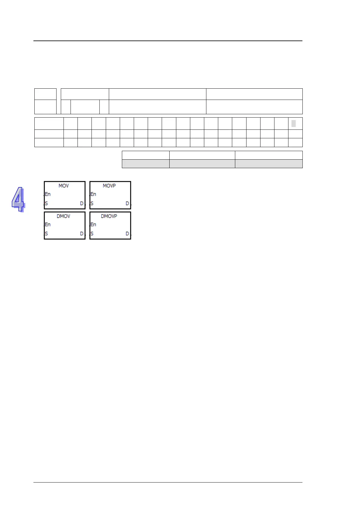
8. The description of the symbols representing the instruction MOV in ISPSoft:
MOV, MOVP, DMOV, and DMOVP: Instruction codes
En: Enable
S: The data source (The applicable format of the operand is a word/double word.)
D: The data destination (The applicable format of the operand is a word/double word.)
The composition of applied instructions:
Some applied instructions are composed of instruction codes. For example, the instructions EI, DI,
WDT, and etc. however, most applied instructions consist of instruction codes and several

 Loading...


