Chapter 4 Instruction Structure
4-9
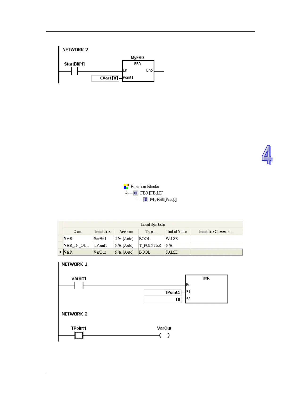
Network 2: When StartBit[1] is ON, the address of CVar1[0] is transmitted to Point1 in FB0.
When VarBit1 in FB0 is ON, E0=1, Var1=CVar1[0], Point1@E0=CVar1
(0+1)=Cvar1[1], and Var2=CVar1[1].
4.5 Pointer Registers of Timers
ISPSoft supports the function blocks. If users want to use the timer in the function block, they
have to declare a pointer register of the timer in the function block. The address of the timer is
transmitted to the pointer register of the timer when the function block is called.
When the variable declaration type is VAR_IN_OUT, and the data type is T_POINTER, the
variable is the pointer register of the timer. The value in the pointer register of the timer can
refer directly to the value stored in the device T or in the variable which is the timer in ISPSoft.
Users can declare 8 pointer registers of the timers in every function block. The range is
TR0~TR7.
If users want to use an instruction in the function block, and the timer is supported among the
operands, users have to use the pointer register of the timer.
Example:
1. Establish a program organization unit (POU) in ISPSoft first.
2. Establish a function block which is called FB0.
3. Declare the varaible in the function block FB0.
Choose VAR_IN_OUT as the declaration type, TPoint1 as the identifier, T_POINTER as the
data type. The variable is the pointer register of the timer.
4. The program in the function block FB0
5. Declare the variable in the program organization unit (POU).
The data type of CVar1 should be TIMER.

 Loading...


