AH500 Programming Manual
7-22
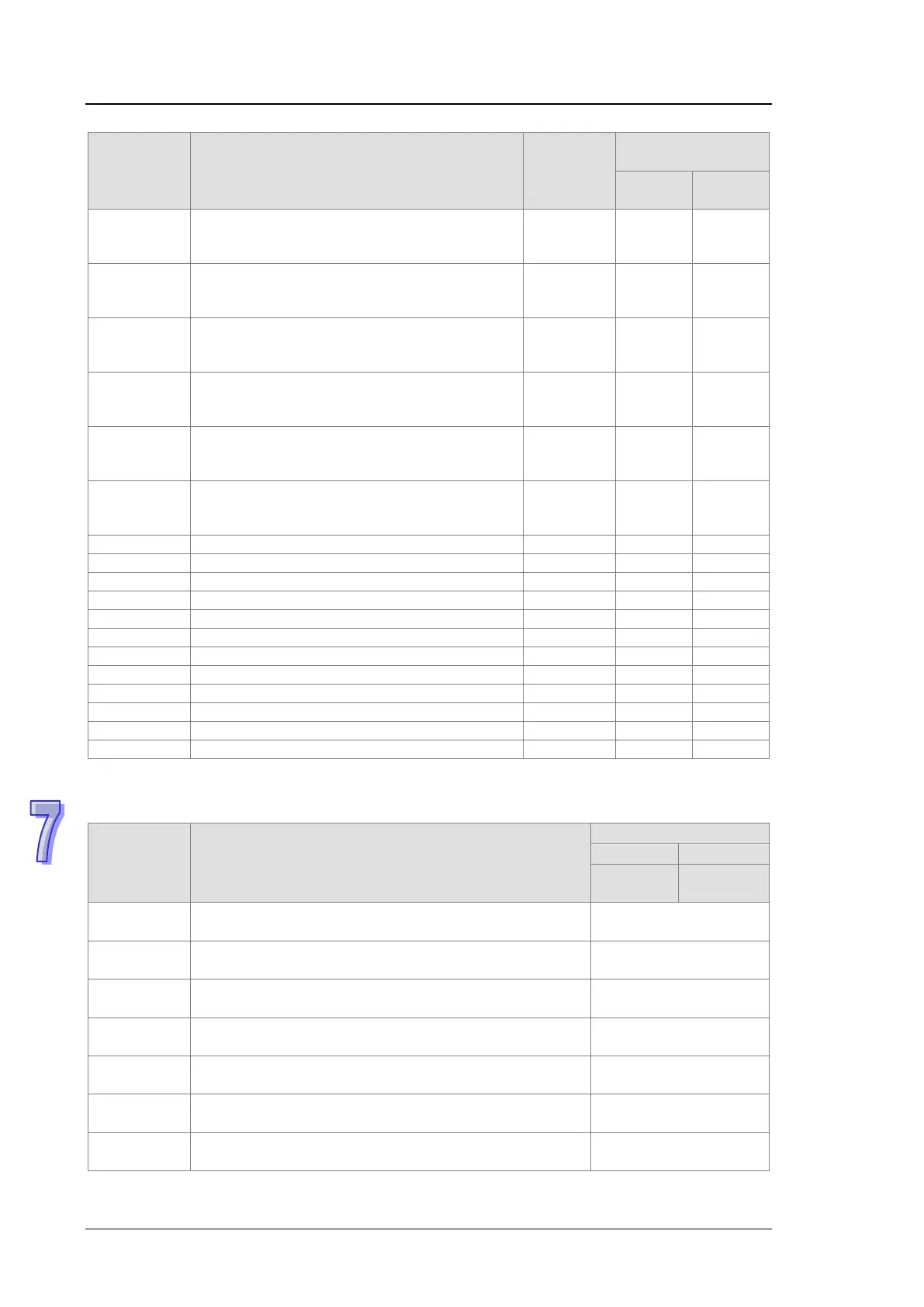
Error code Description
CPU
Status
ERROR
16#E286
The network module IP of the control mode
CPU on the main backplane slot 6 cannot be
Continue Keep Keep
16#E287
The network module IP of the control mode
CPU on the main backplane slot 7 cannot be
Continue Keep Keep
16#E288
The network module IP of the control mode
CPU on the main backplane slot 8 cannot be
Continue Keep Keep
16#E289
The network module IP of the control mode
CPU on the main backplane slot 9 cannot be
Continue Keep Keep
16#E28A
The network module IP of the control mode
CPU on the main backplane slot 10 cannot be
Continue Keep Keep
16#E28B
The network module IP of the control mode
CPU on the main backplane slot 11 cannot be
Continue Keep Keep
Connection in use or duplicate forward open
Target for connection not configured
Non-Listen only connection not opened
Invalid Originator to Target Size
Invalid Target to Originator Size
Invalid Configuration path
Consuming symbol does not exist
Producing symbol does not exist
7.1.2
Analog I/O Modules and Temperature Measurement
Modules
Error code Description
ERROR
16#A000
The signal received by channel 0 exceeds the range of
inputs which can be received by the hardware.
Blinking
16#A001
The signal received by channel 1 exceeds the range of
inputs which can be received by the hardware.
Blinking
16#A002
The signal received by channel 2 exceeds the range of
inputs which can be received by the hardware.
Blinking
16#A003
The signal received by channel 3 exceeds the range of
inputs which can be received by the hardware.
Blinking
16#A004
The signal received by channel 4 exceeds the range of
inputs which can be received by the hardware.
Blinking
16#A005
The signal received by channel 5 exceeds the range of
inputs which can be received by the hardware.
Blinking
16#A006
The signal received by channel 6 exceeds the range of
inputs which can be received by the hardware.
Blinking

 Loading...


