AH500 Programming Manual
2-52
register, i.e. (D+3, D+2, D+1, D) in which the register whose number is smaller represents the lower
16 bits. The highest bit represents either a positive sign or a negative sign, and the values which can
be stored in the data registers range from -9,223,372,036,854,776 to +9,223,372,036,854,775,807.
The data registers also can be used to refresh the values in the control registers in the modules
other than digital I/○ modules. Please refer to ISPSoft User Manual for more information regarding
refreshing the values in the control registers.
The registers can be classified into two types according to their properties:
1. General-purpose register: If the PLC begins to run, or is disconnected, the value in the register
will be cleared to zero. If users want to retain the data when the PLC begins to RUN, they can
refer to ISPSoft User Manual for more information. Please notice that the value will still be
cleared to zero if the PLC is disconnected.
2. Latched register: If the PLC is disconnected, the data in the latched register will not be cleared.
In other words, the value before the disconnection is still retained. If users want to clear the data
in the latched area, they can use RST or ZRST.
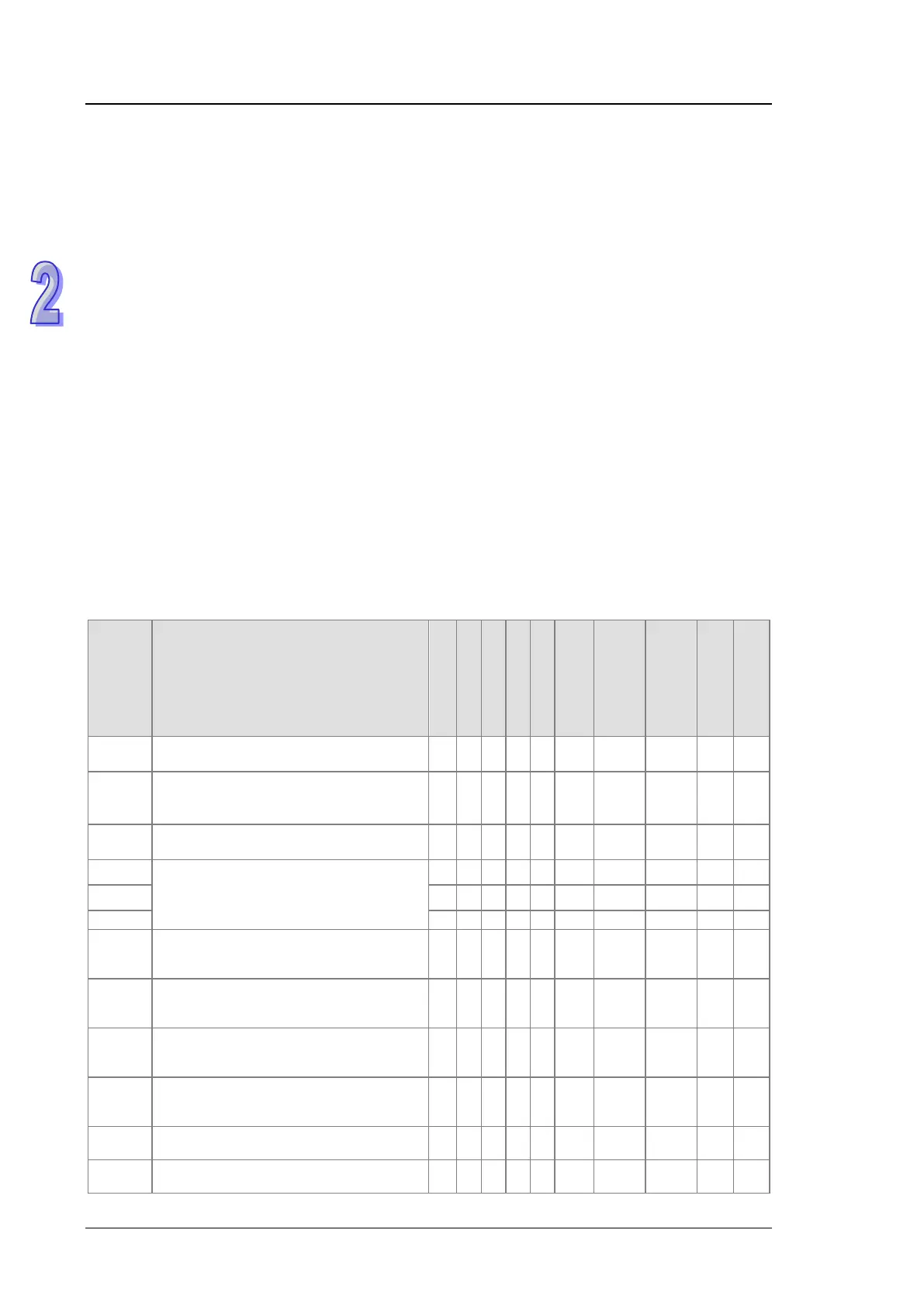
2.2.14 Special Data Registers
Every special data register has its definition and specific function. The system statuses and the error
messages are stored in the special data registers. Besides, the special data registers can be used
to monitor the system statuses. The special data registers and their functions are listed as follows.
As to the SR numbers marked “*”, users can refer to the additional remarks on special auxiliary
relays/special data registers. The “R” in the attribute column indicates that the special data register
can read the data, whereas the “R/W” in the attribute column indicates that it can read and write the
data. In addition, the mark “–” indicates that the status of the special data register does not make
any change. The mark “#” indicates that the system will be set according to the status of the PLC,
and users can read the setting value and refer to the related manual for more information.
SR Function
CPU5×0-RS2
CPU5×0-EN
CPU5×1-RS2
OFF
ON
STOP
RUN
RUN
STOP
Attribute
Default
SR0
Error-detecting code of the PLC operation
error
○ ○ ○ ○ ○ 0 0 – R 0
↓
SR2
The address of the operation error is
locked.
○ ○ ○ ○ ○ 0 0 – R 0
SR4
Error-detecting code of the grammar check
error
○ ○ ○ ○ ○ 0 0 – R 0
Address of the instruction/operand check
error
Step address at which the watchdog timer
○ ○ ○ ○ ○ 0 0 – R 0
○ ○ ○ ○ ○ 0 0 – R 0
↓
Data amount from the last cyclic
synchronization (Kbyte)
× × × × ○
0 – – R 0
↓
Maximum synchronized data amount
(Kbyte)
× × × × ○
0 – – R 0
↓
Noncyclic synchronization time (ms)
× × × × ○
0 – – R 0
↓
Cyclic synchronization time (ms)
× × × × ○
0 – – R 0
*SR32 Status of the master power module
○ ○ ○
– – – R 0
*SR33 Status of the standby power module
○ ○ ○
– – – R 0

 Loading...


