Chapter 6 Applied Instructions
6-501
6.22.2 Explanation of Ethernet Instructions
API
Instruction code Operand
Function
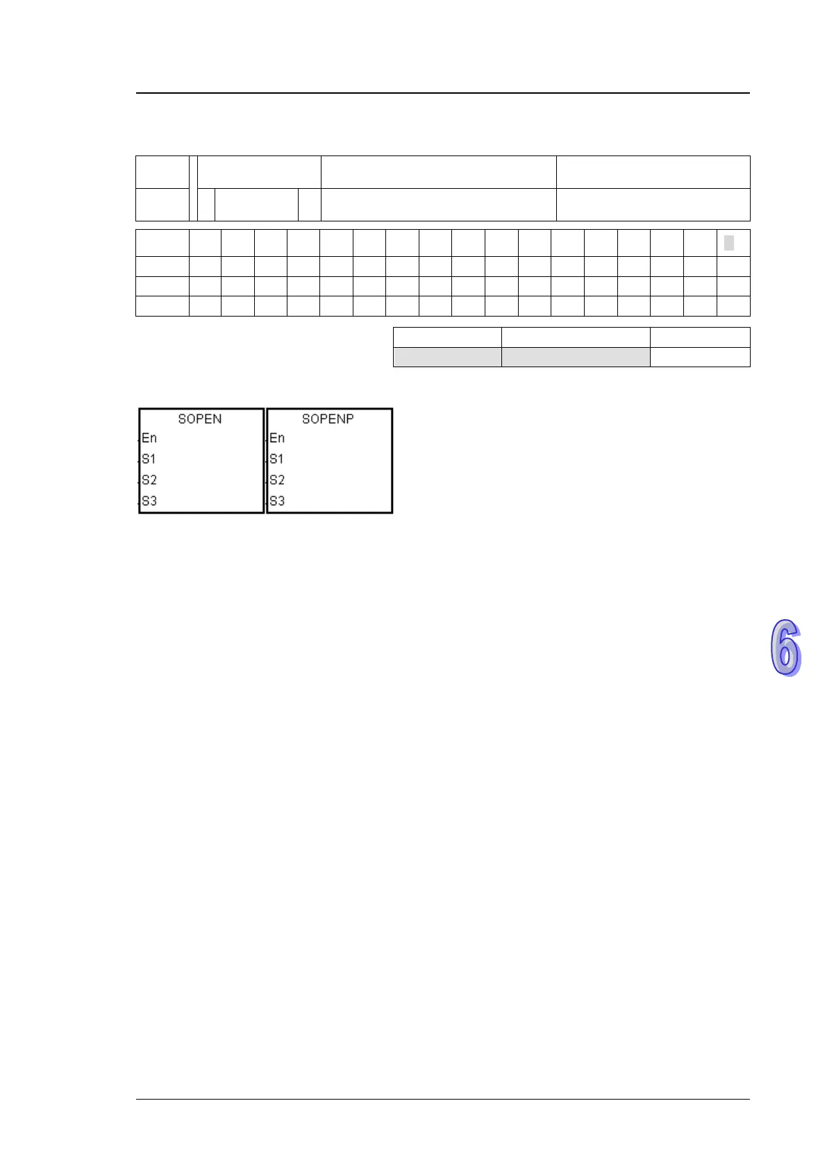
2200 SOPEN P
S
1
, S
2
, S
3
Opening the socket
Device
X Y M S T C HC D L SM SR E PR K 16# “$” DF
Pulse instruction 16-bit instruction (7 steps
32-bit instruction
AH500 AH500 -
Symbol:
S
1
:
Socket mode Word
S
2
:
Socket number Word
S
3
:
Start mode Word
Explanation:
1. S
1
is 1 if users want to open the TCP socket, and S
1
is 0 if users want to open the UDP socket.
S
2
is the socket number. The AH500 series PLC as the client sends the TCP connection
request to the server if S
3
is 1, and the AH500 series PLC as the sever waits for the TCP
connection request from the client if S
3
is 0. If users want to start the UDP connection, S
3
can
be 0 or 1.
2. The operand S
1
should be either 0 or 1; the operand S
2
should be within the range between 1
and 8; the operand S
3
should be either 0 or 1.
3. Before using the instruction, users have to accomplish the following setting in HWCONFIG of
ISPSoft or using the instruction MOV to transfer the data related to the sockets to the
corresponding special data registers.
PLC Parameter Setting→Ethernet-Basic→Setting the IP addres and the netmask
address
PLC Parameter Setting→Ethernet-Advance→Socket→Enable Socket Function
PLC Parameter Setting→Ethernet-Advance→Socket→TCP/UDP Socket Connection→
Setting the sockets which are used.
4. Users can set the sockets which uses the TCP protocol to execute the data exchange. The
values in all registers can be altered except that the transmitted data counter and the received
data counter are read-only counters.

 Loading...


