AH500 Programming Manual
4-4
The values of the operands used in the instructions can be divided into the 32-bit values and the
64-bit values. Accordingly, in order to process data of difference lengths, the instructions are divided
into the 32-bit instructions and the 64-bit instructions. To separate the 64-bit instruction from the
32-bit one, a D is added in front of the 32-bit instruction.
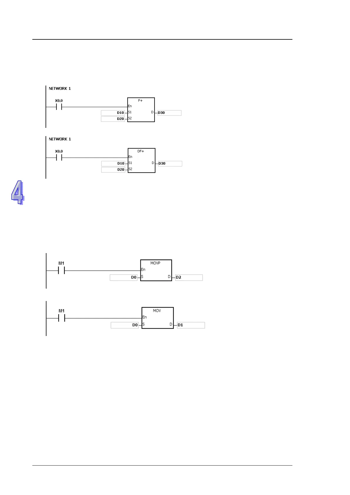
32-bit single-precision floating-point number instruction F+
When X0.0 is ON, the data in
(D11, D10) and (D21, D20) is
transferred to (D31, D30).
64-bit double-precision floating-point number instruction DF+
When X0.0 is ON, the data in
(D13, D12, D11, D10) and
(D23, D22, D21, D20) is
transferred to (D33, D32, D31,
D30).
The continuous execution of the instruction and the pulse execution of the instruction:
1. The execution of the instructions can be divided into the continuous execution and the pulse
execution. When the instruction is not executed, the time needed to execute the program is
shorter. Therefore, using the pulse instruction in the program can lessen the scan cycle.
2. The pulse function allows the related instruction to enable the rising edge-triggered control
input. The instruction is ON within one scan cycle.
3. If the control input stays ON, and the related instruction is not executed, the control input has
to be switched from OFF to ON again in order to execute the instruction.
4. The pulse instruction:
Pulse execution
When M1 is switched from
OFF to ON, the instruction
MOVP is executed once. The
instruction is not executed
any more within the scan
cycle. Therefore, it is called
the pulse instruction.
Whenever M1 is ON during
the scan cycle, the instruction
MOV is executed once.
Therefore, the instruction is
called the continuous
instruction.
When the conditonal contact M1 is OFF, the instruction is not executed, and the value in the
destination operand D does not change.
The objects that the operands designate:
1. Input relay: X0.0~X511.15 or X0~X511
2. Output relay: Y0.0~Y511.15 or Y0~Y511
3. Internal relay: M0~M8191
4. Stepping relay: S0~S2047
5. Timer: T0~T2047
6. 16-bit counter: C0~C2047
7. 32-bit counter: HC0~HC63
8. Data register: D0~D65535 or D0.0~D65535.15
9. Link register: L0~L65535 or L0.0~D65535.15
10. Special auxiliary flag: SM0~SM2047
11. Special data register: SR0~SR2047
12. Index register: E0~E31

 Loading...


