Chapter 6 Applied Instructions
6-213
API
Instruction code
Operand Function
D
OR#
S
1
, S
2
Contact type of logical operation OR#
Device
X Y M S T C HC D L SM SR E PR K 16#
“$” DF
Pulse instruction
16-bit instruction (5 steps)
32-bit instruction (5 steps)
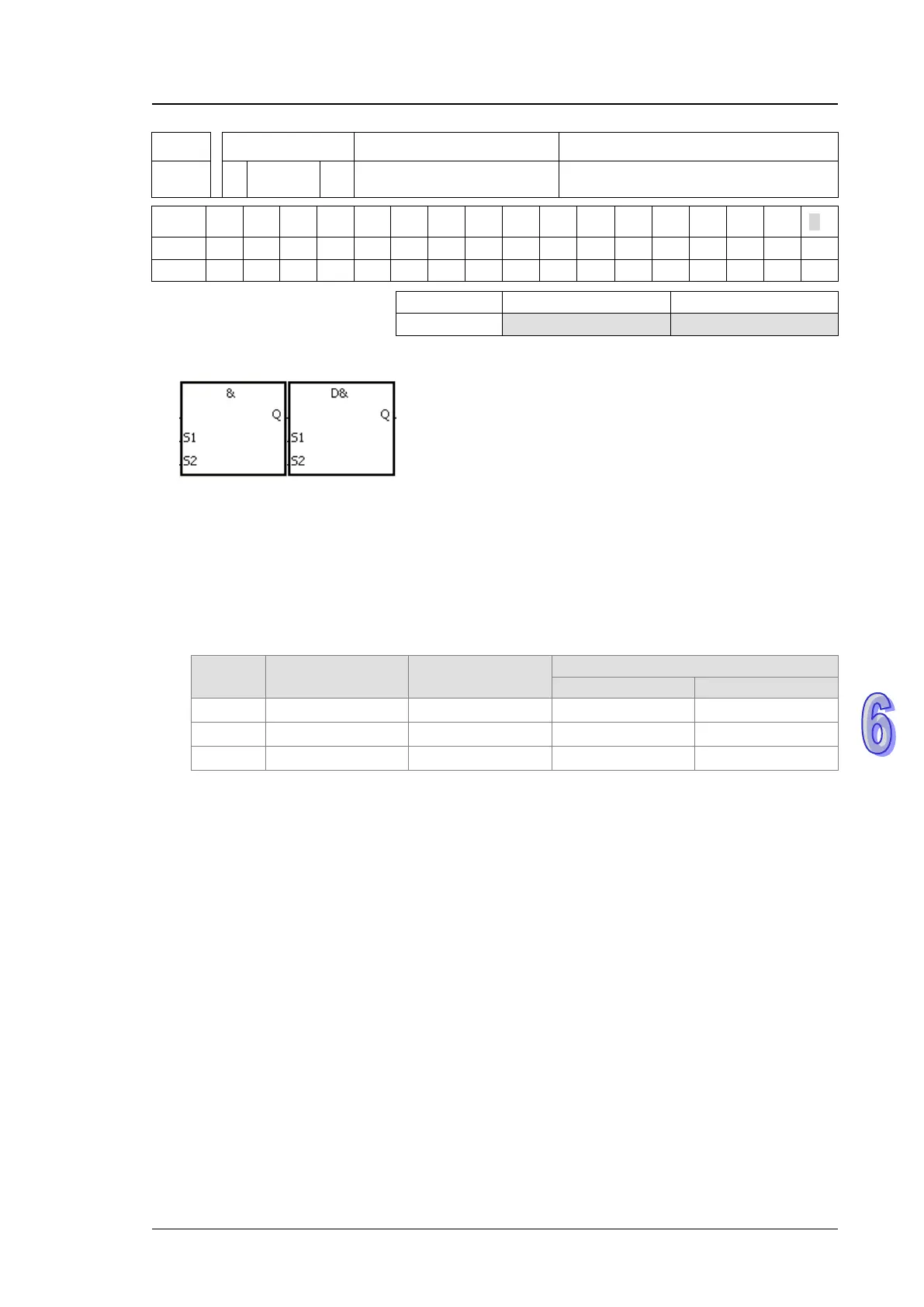
Symbol:
Taking OR& and DOR& for example
S
1
:
Data source 1 Word/Double word
S
2
:
Data source 2 Word/Double word
Explanation:
1. The instruction is used to compare the data in S
1
with that in S
2
. When the comparison result is
not 0, the condition of the instruction is met. When the comparison result is 0, the condition of
the instruction is not met.
2. Only the instruction DOR# can use the 32-bit counter.
3. The instruction OR# and the contact are connected in parallel.
API No. 16-bit instruction 32-bit instruction
Comparison operation result
1
2
1
2
1
|
2
0
1
2
1
2
1
2
4. &: Logical AND operation
5. |: Logical OR operation
6. ^: Logical exclusive OR operation
Example:
1. When X0.1 is ON, Y0.0 is ON. Besides, when the logical operator AND performs the logical
AND operation on each pair of corresponding bits in C0 and C10 and the operation result is not
0, Y0.0 is ON.
2. When X0.2 and X0.3 are ON, Y0.1 is ON. When the logical operator OR performs the logical
OR operation on each pair of corresponding bits in the 32-bit register (D10, D11) and the 32-bit
register (D20, D21) and the operation result is not 0, Y0.1 is ON. Besides, when the logical
operator XOR performs the logical exclusive OR operation on each pair of corresponding bits in
the 32-bit counter HC0 and the 32-bit register (D200, D201) and the operation result is not 0,
Y0.1 is ON.

 Loading...


