Chapter 6 Applied Instructions
6-383
API Instruction code Operand
Function
1702 DSW
S, D
1
, D
2
, n
DIP switch
Device
X Y M S T C HC D L SM SR E PR K 16# “$” DF
Pulse instruction
16-bit instruction (9 steps)
32-bit instruction
- AH500 -
Symbol:
S
1
:
Initial input device Bit
S
2
:
For system use only Word
D
1
:
Initial output device Bit
D
2
:
Device in which the value is stored Word
n
:
Number of DIP switches Word
Explanation:
1. The four or eight external inputs starting from the input specified by S
1
are connected to the
four external outputs starting from the output specified by D
1
to form a four-digit DIP switch or
two four-digit DIP switches. The value that users enter by pressing the DIP switch is stored in
D
2
. Whether there is one four-digit DIP switch or two four-digit DIP switches depends on n.
2. If n is 1, the operand D
2
occupies one register. If n is 2, the operand D
2
occupies two registers.
3. S
2
and S
2
+1, which are for system use only, occupy two devices. Please do not alter the
values in these devices.
4. After the execution of the instruction is complete, SM694 is ON for a scan cycle.
5. When the conditional contact is not enabled, the four external outputs starting from the output
specified by D
1
keep OFF.
6. When the on-line editing is used, please reset the conditional contact to initialize the
instruction.
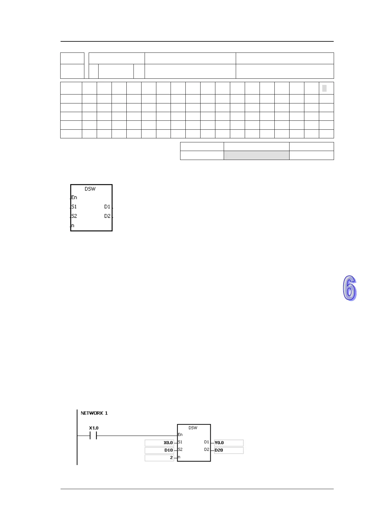
Example:
1. X0.0~X0.3 are connected to Y0.0~Y0.3 to form the first DIP switch, and X0.4~X0.7 are
connected to Y0.4~Y0.7 to form the second DIP switch. When X1.0 is ON, the instruction is
executed. The value that users enter by pressing the first DIP switch is converted into the
binary value, and the conversion result is stored in D20. The value that users enter by pressing
the second DIP switch is converted into the binary value, and the conversion result is stored in
D21.

 Loading...


