Chapter 6 Applied Instructions
6-431
API Instruction code Operand
Function
1902 GPWM
S
1
, S
2
, D
General pulse width modulation
Device
X Y M S T C HC D L SM SR E PR K 16# “$” DF
16-bit instruction (7 steps)
Symbol:
S
1
:
Pulse width Word
S
2
:
Pulse cycle Word
D
:
Output device Bit
Explanation:
1. When the instruction GPWM is executed, every pulse with a width specified by S
1
and with a
cycle specified by S
2
is output from the device specified by D.
2. The pulse width specified by S
1
is t. t should be within the range between 0 and 3276
milliseconds.
3. The pulse cycle specified by S
2
is T. T should be within the range between 1 and 32767
milliseconds, and S
1
should be less than S
2
.
4. S
2
+1 and S
2
+2 are parameters for system use. Please do not occupy them.
5. If S
1
is less than 0, there is no pulse output. If S
1
is larger than S
2
, the output device keeps ON.
6. S
1
and S
2
can be altered during the execution of the instruction GPWM.
7. If the conditional contact is not enabled, there is no pulse output.
8. When the on-line editing is used, please reset the conditional contact to initialize the
instruction.
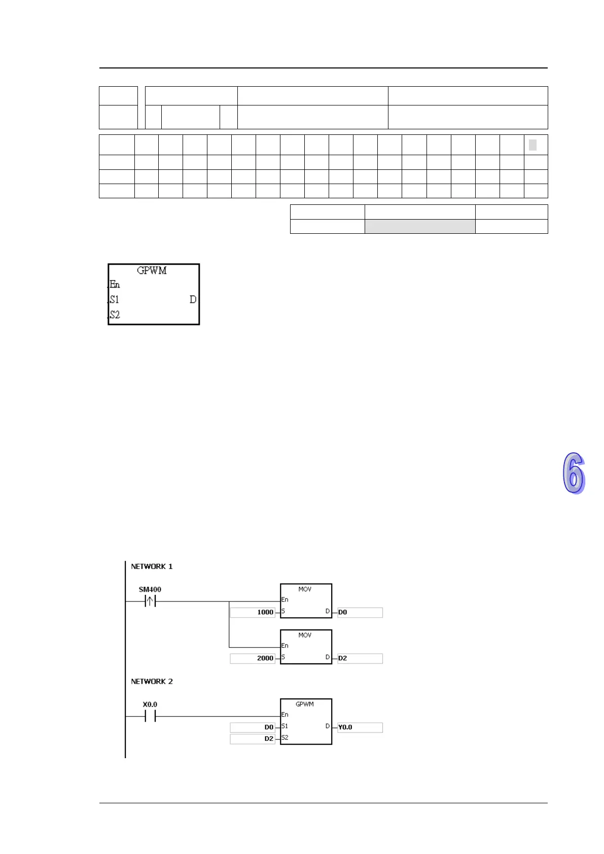
Example:
When the program is executed, the values in D0 and D2 are 1000 and 2000 respectively. When
X0.0 is ON, the pulses illustrated below are output from Y0.0. When X0.0 is OFF, Y0.0 is OFF.

 Loading...


