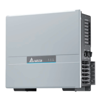
3. Route the cable through the inverter as illustrated and
connect it to the RS485 terminal block of the communica-
tion card.
Red VCC
Black GND
Yellow D+ (DATA+)
Blue D– (DATA–)
þ
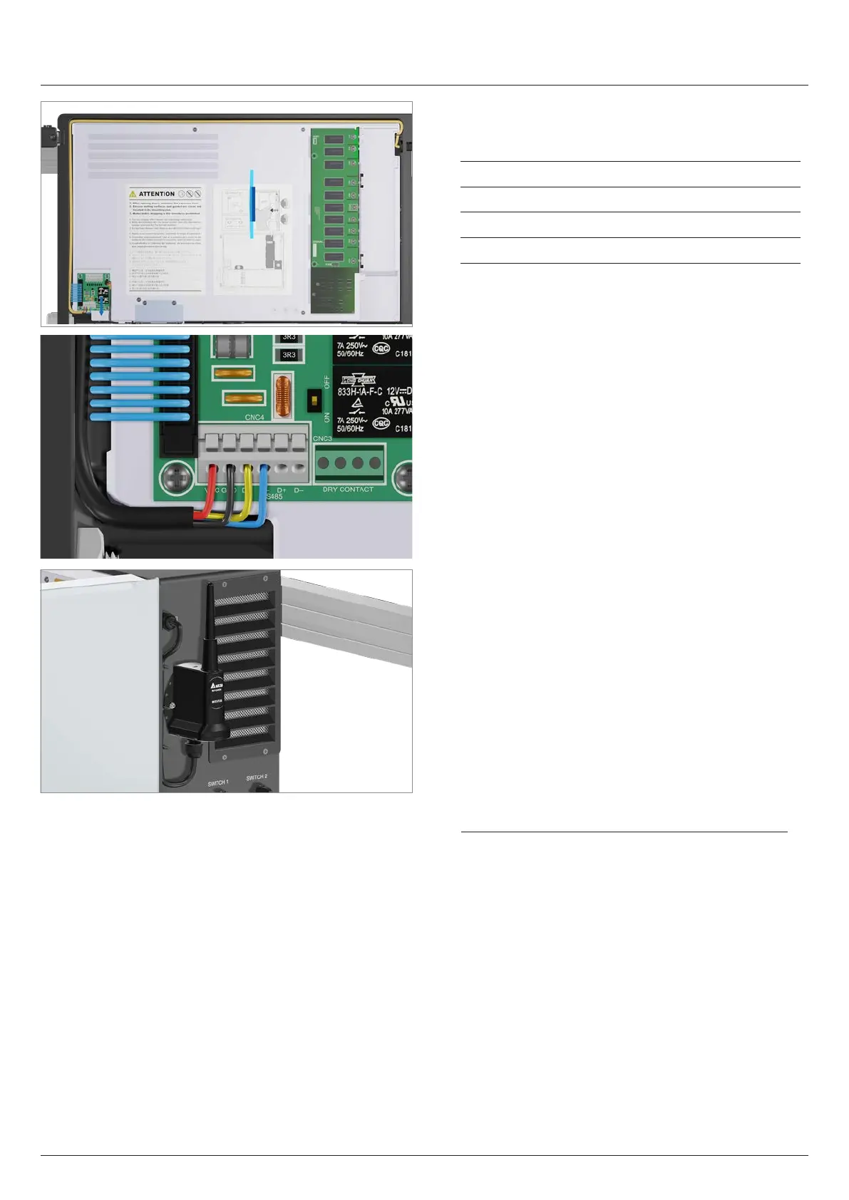
Installation of the Wi-Fi module is complete.
4. To complete the work, follow the instructions in the chapter
“12. Recommissioning the inverter after work”, page 143.
11 Replacing or cleaning components, installing accessories
Installing/replacing the Wi-Fi module
142
Installation and Operation Manual M50A_260 RPI503M260000 Product version L and M EU V1.3 EN 2023-08-14
 Loading...